Plans Sections Diagrams

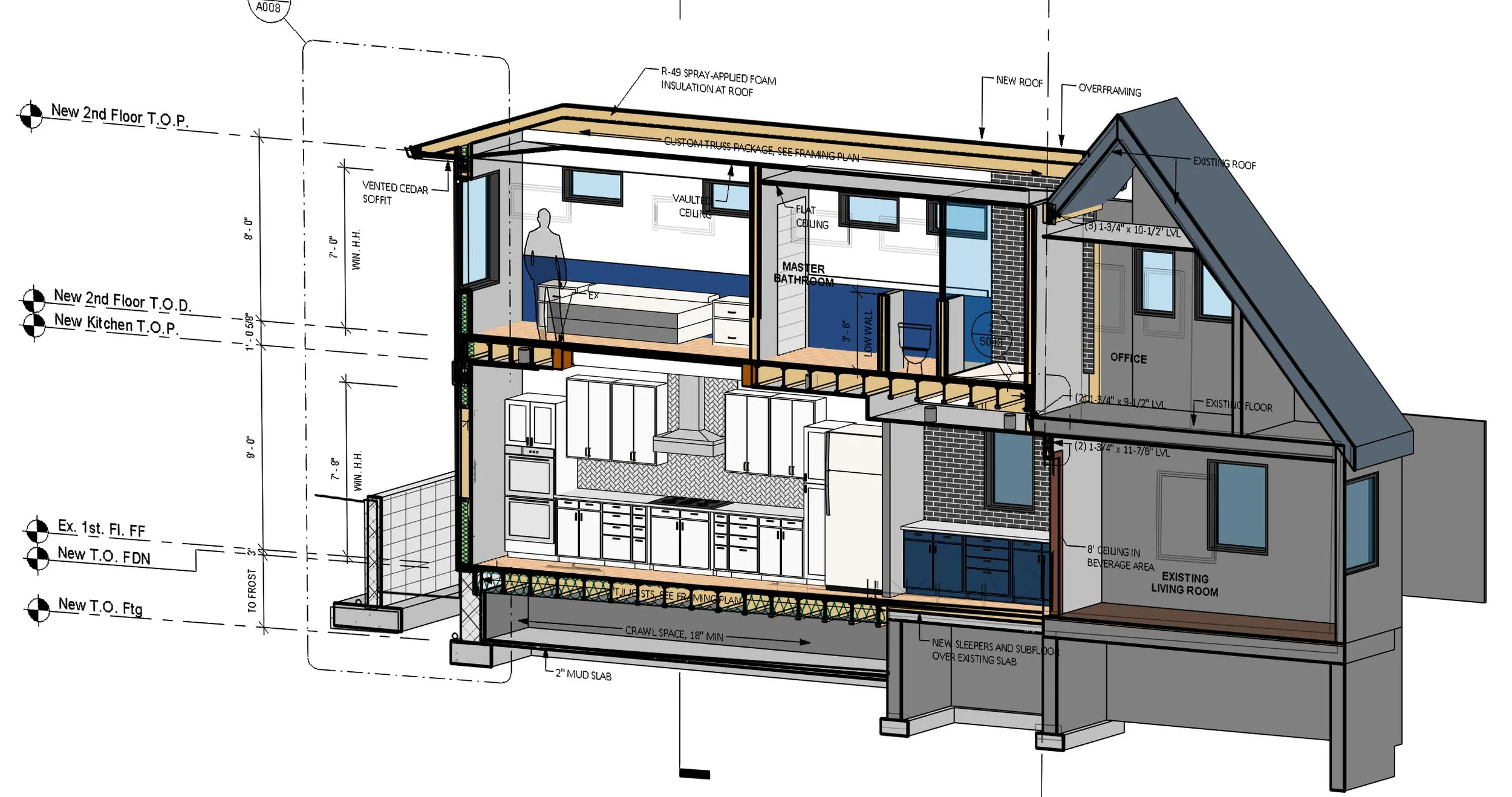
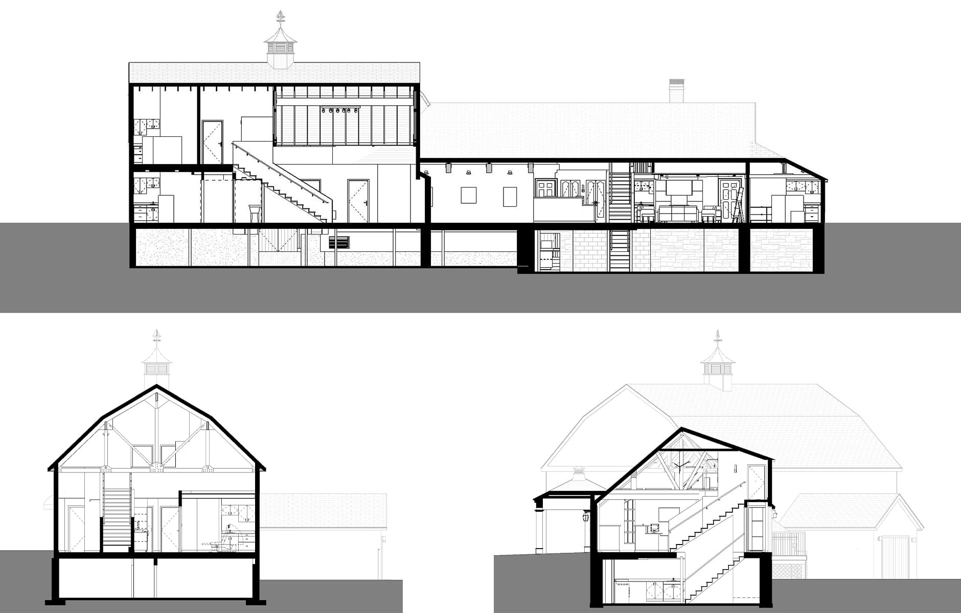
How To Read Sections вђ Mangan Group Architects Residential And Plan, section, and elevation are different types of drawings used by architects to graphically represent a building design and construction. a plan drawing is a drawing on a horizontal plane showing a view from above. an elevation drawing is drawn on a vertical plane showing a vertical depiction. a section drawing is also a vertical depiction. A section drawing is very similar, with the layers and stories on full display. whether it’s a full building section, or a small joinery detail, the principle remains the same. for a typical building section, you’ll likely see a mixture of ground, structural elements, and architectural features.

Why Are Architectural Sections Important To Projects Patriquin 7. structural architectural diagram. represented through either planimetric, sectional and or axonometric diagrams, this kind of diagram shows either the physical structure of a building, or how invisible forces such as tension and compression act on the structure of a building. 8. scaled architectural diagram. A section is an orthographic 2d drawing that uses an imaginary vertical plane to “cut” the building. on one side of the plane, the building is removed so that the construction of whatever is sliced can be seen. the slice is typically made perpendicular to the wall it is cutting through. it may or may not show the building elements in. Sections and elevations are always drawn with the ground plane cut through in section. elements cut in plan and section (ie. wall type and thickness, doors, windows) should be drawn the same way, as they are representing the same thing. internal elevation information is secondary in sections and should generally be indicative. In a standard set of architectural plans on a small residential project, the elevations will most likely be a set of drawings from the main facades of the building. for example, front, back and two sides – or north, south, east and west. the sections would most likely be two or more sections cut at 90 degrees of one another to give.

Comments are closed.