Pwm Dc Motor Control Circuit Diagram

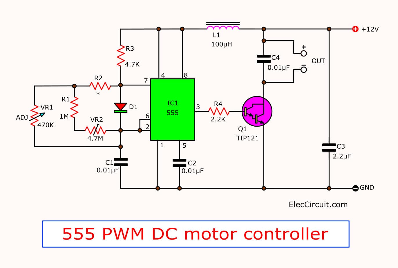
555 Pwm Dc Motor Controller Circuit Eleccircuit Description. h ere is a simple pwm motor speed controller circuit that can be used for varying the speed of low power dc motors . the variation in speed is achieved by varying the duty cycle of the pulse supplied to drive the motor. of the two gates of ic cd40106b , n1 is wired as an inverting schmitt trigger astable multi vibrator for. 5 simple dc motor speed controller circuits explained.

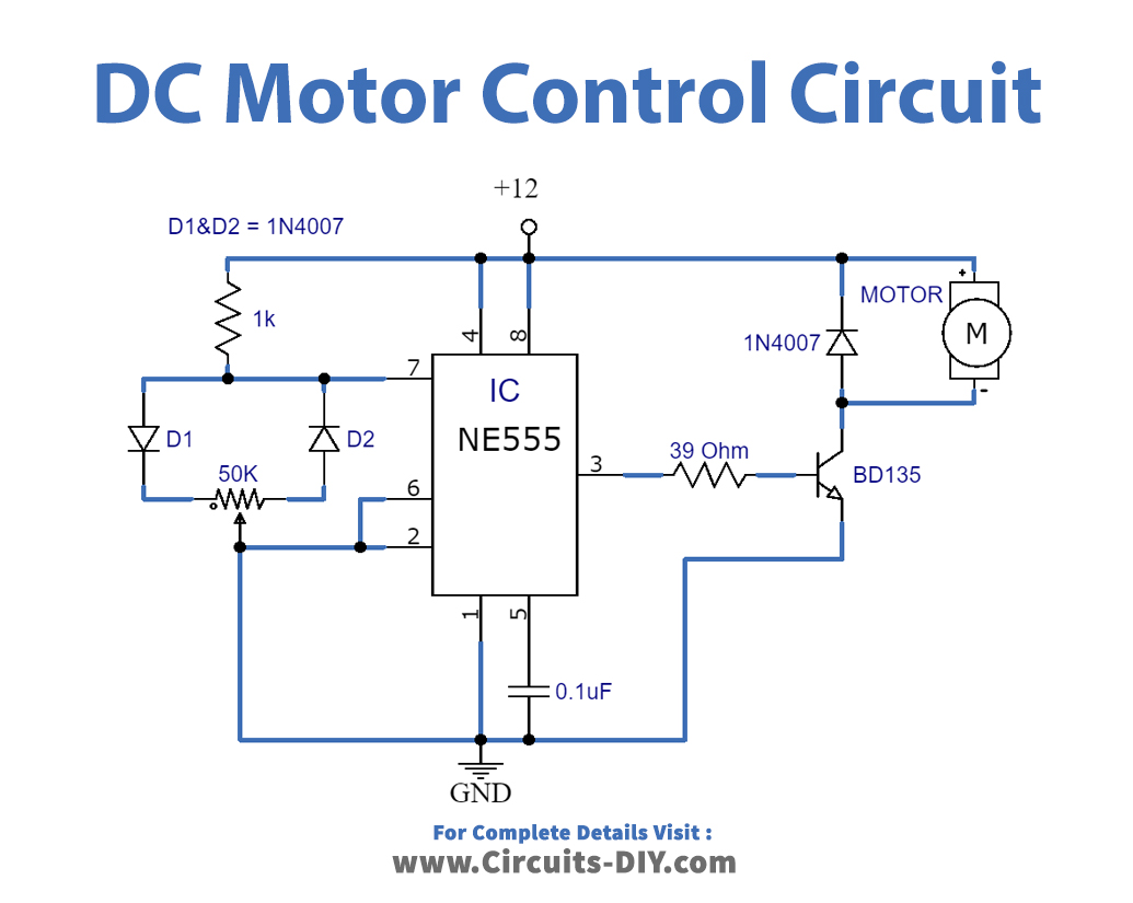
Dc Motor Control Pwm With 555 Pulse width modulation used for motor control. H bridge dc motor control using complementary pwm. Working explanation. in this dc motor speed control pwm circuit timer, ic 555 is working as a square pulse generator depending on the value of the potentiometer. the output pulse width or duty cycle can get change and the output from ic 555 is immediately given to the motor driver h bridge ic (h bridge is a setup that is employed to drive or. Principle of operation of a pulse width modulator (pwm) amplifier. let’s consider the figure below: pulse width modulation of a dc motor . a dc power supply voltage is rapidly switched at a fixed frequency f between two values i.e. on and off.

Comments are closed.