Radiator Electric Fan Wiring Diagram

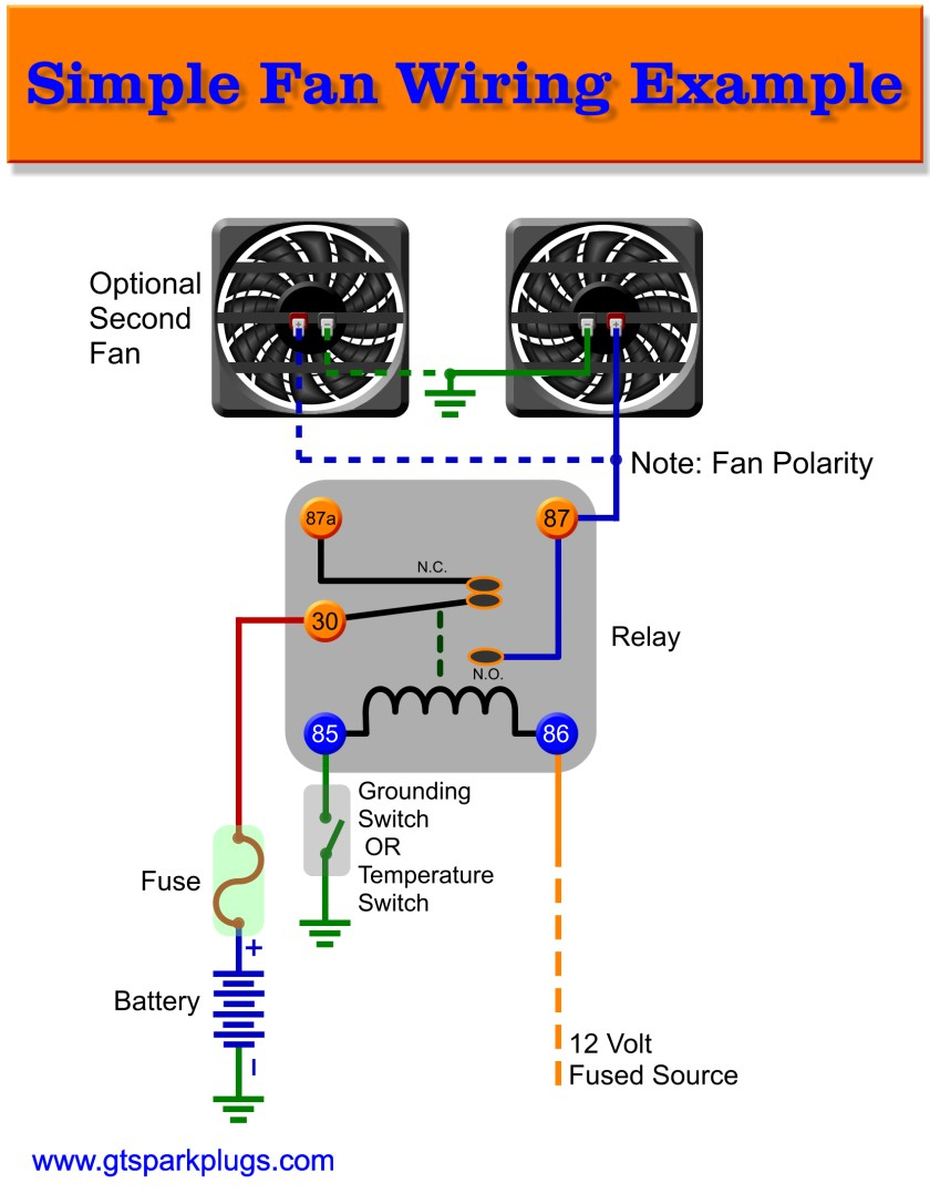
Wiring Diagram For Electric Radiator Fan Wiring Diagram How to wire an electric radiator fan relay temp sensor. With dual cooling fans, there are two methods for wiring up the relay kit. this is based on the draw from the fans, if the fans are larger and draw more than 15 amps each, it's recommended to install a second relay kit as shown below. for smaller fans, both fans can be connected to a single relay as shown above, and the proper fuse should be.

Radiator Fan Wiring Diagram How to wire dual electric cooling fans. Locate a suitable location for mounting the electric fan. this is typically on the front side of the radiator, but can vary depending on the vehicle. ensure that the fan is securely mounted and positioned to provide optimal air flow through the radiator. determine the power source for the fan. in most cases, this will be the vehicle’s battery. Step 3: install the electric fan relay. after wiring the electric fan to the proper power source, the next step is to install the electric fan relay. the electric fan relay is an important component that controls the operation of the electric fan. it acts as a switch, turning the fan on and off when needed. Start your wiring project by taking both of the positive wires from the fans and run them to the yellow wires on each relay (tab 87). then connect switched power (usually from your ignition switch), to the blue wires on both relays (tab 86). next, splice together both black wires from the relays (tab 85) and connect them to the thermostat.

Wiring Diagram For Auto Electric Radiator Fan Step 3: install the electric fan relay. after wiring the electric fan to the proper power source, the next step is to install the electric fan relay. the electric fan relay is an important component that controls the operation of the electric fan. it acts as a switch, turning the fan on and off when needed. Start your wiring project by taking both of the positive wires from the fans and run them to the yellow wires on each relay (tab 87). then connect switched power (usually from your ignition switch), to the blue wires on both relays (tab 86). next, splice together both black wires from the relays (tab 85) and connect them to the thermostat. 30: constant 12v, unswitched 85: signal (switched 12v) 86: ground (completes circuit) 87: consumer (fan) 12v 87b: extra consumer (same as 87) 12v switched wire. may be green wire at a c clutch. note: or in an ’84 to ‘89 240 you may use the a c power ‘on’ wire: red white wire at ac switch microswitch in dash. Wire the relay to the power source: connect the relay’s positive wire to the power source, usually the positive terminal of the battery. connect the relay’s negative wire to a suitable ground connection. test the fan: after completing the wiring process, test the electric cooling fan to ensure proper functionality.

Comments are closed.