Relay Contactor Interlock Circuit Wiring Ato

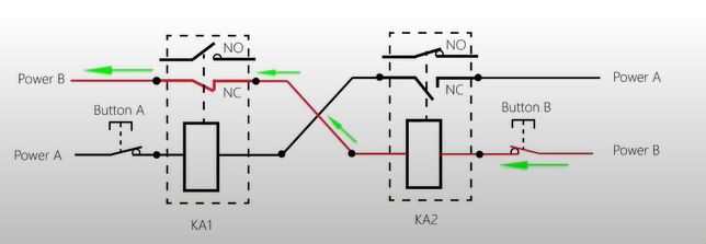
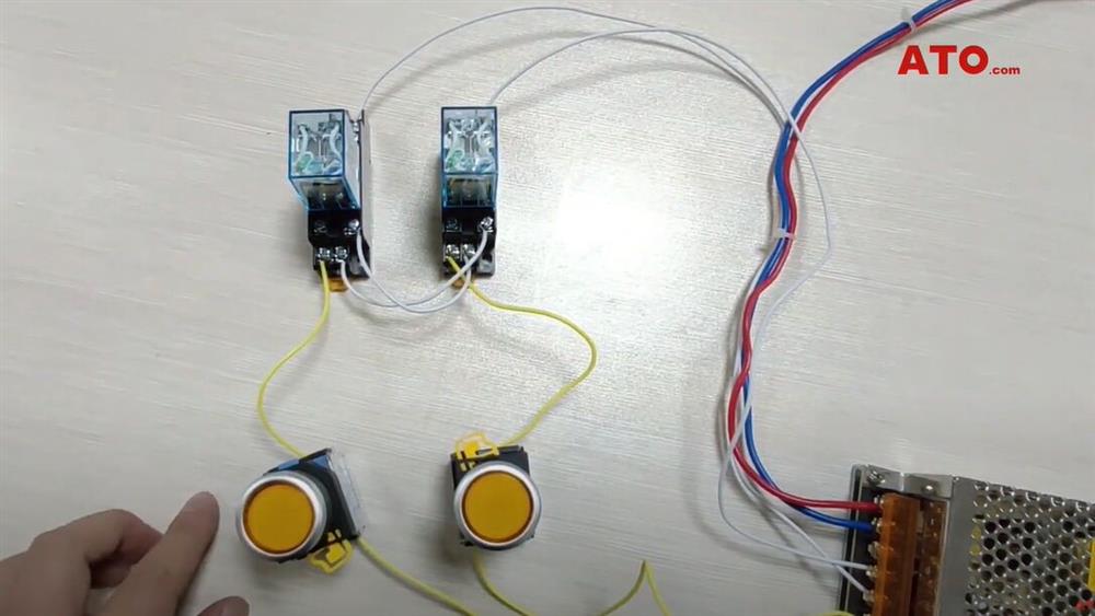
Relay Contactor Interlock Circuit Wiring Ato Relay contactor interlock circuit. ka1 and ka2 respectively connect the circuit in series to the normally closed (nc) contact of each other. when ka1 is powered on, the normally closed (nc) contact of ka1 is disconnected. no matter whether button b is closed or not, ka2 cannot pass current. Its logic is: when a acts, b cannot act, and when b acts, a cannot act. therefore, it is often used in safety circuits to ensure that two unrelated electrica.

Relay Contactor Interlock Circuit Wiring Ato Ato relay video; relay videos relay contactor interlock circuit wiring. how to use digital timer relay? 3 phase monitoring relay phase failure & sequence test. To wire an interlocking contactor, you’ll need a few basic tools and materials, including wire strippers, a screwdriver, and the appropriate wiring terminals. additionally, a step by step diagram will serve as your guide throughout the process. this diagram will outline the connections and terminals that need to be made to ensure the. Step 1: begin by gathering all the necessary tools and materials for the wiring process. this may include a contactor relay, a power supply, control wires, electrical connectors, and a wiring diagram specific to your application. step 2: familiarize yourself with the components of the contactor relay. these typically include the coil, contacts. Connect load. connect the 3 phase load (e.g. distribution board, load center, three phase induction motor etc.) to the output terminals of the changeover switch. 6. wiring the control panel. inside the control panel, wire the circuit breakers, contactors, timer, 14 pin relay or 5 pin relay (according to the system requirement) and any other.

Relay Contactor Interlock Circuit Wiring Ato Step 1: begin by gathering all the necessary tools and materials for the wiring process. this may include a contactor relay, a power supply, control wires, electrical connectors, and a wiring diagram specific to your application. step 2: familiarize yourself with the components of the contactor relay. these typically include the coil, contacts. Connect load. connect the 3 phase load (e.g. distribution board, load center, three phase induction motor etc.) to the output terminals of the changeover switch. 6. wiring the control panel. inside the control panel, wire the circuit breakers, contactors, timer, 14 pin relay or 5 pin relay (according to the system requirement) and any other. What is electrical interlocking? power and control. How to wire 11 pin relay for interlocking & holding circuit?.

Relay Contactor Interlock Circuit Wiring Ato What is electrical interlocking? power and control. How to wire 11 pin relay for interlocking & holding circuit?.

Comments are closed.