Rv Automatic Transfer Switch Wiring Diagram Wiring Diagram

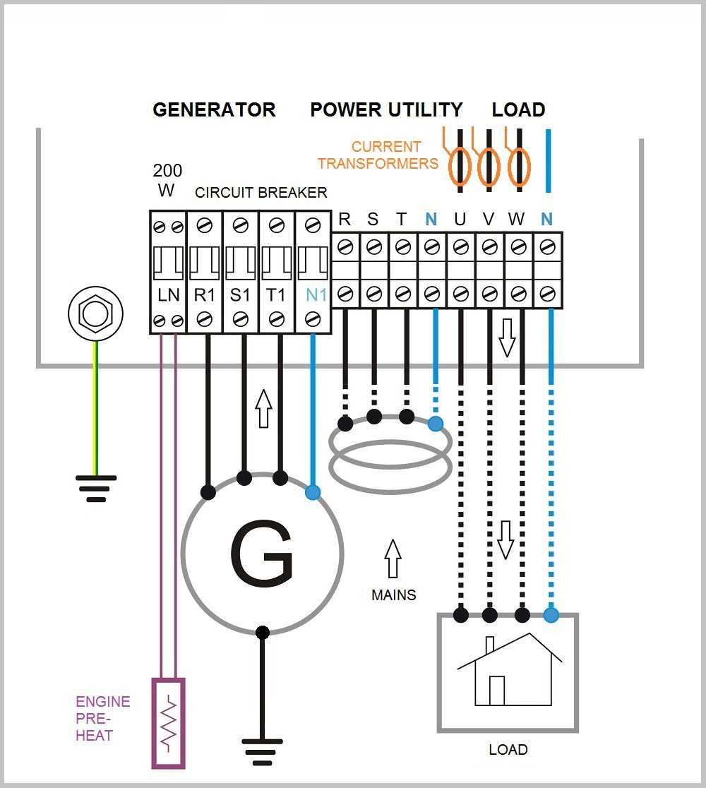
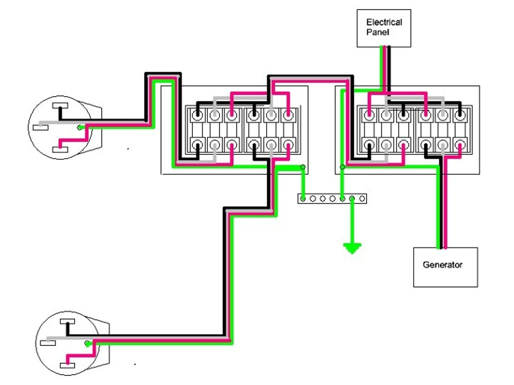
Rv Automatic Transfer Switch Wiring Diagram Complete Wiringођ Test 2: start up your rv’s on board generator. with your meter still set to the 600 volt ac scale, test the incoming power from your generator, which should measure 120 volts from red to white and black to white, and either 0 volts or ~240 volts from black to red, depending on if your generator is wired as 120 120 volts or 120 240 volts. The transfer switch is responsible for routing the power supply between the utility grid and the generator. 3. disconnect the power sources. turn off the main breaker in the electrical distribution panel and disconnect the utility power source. then, turn off the generator and disconnect its power source as well. 4.

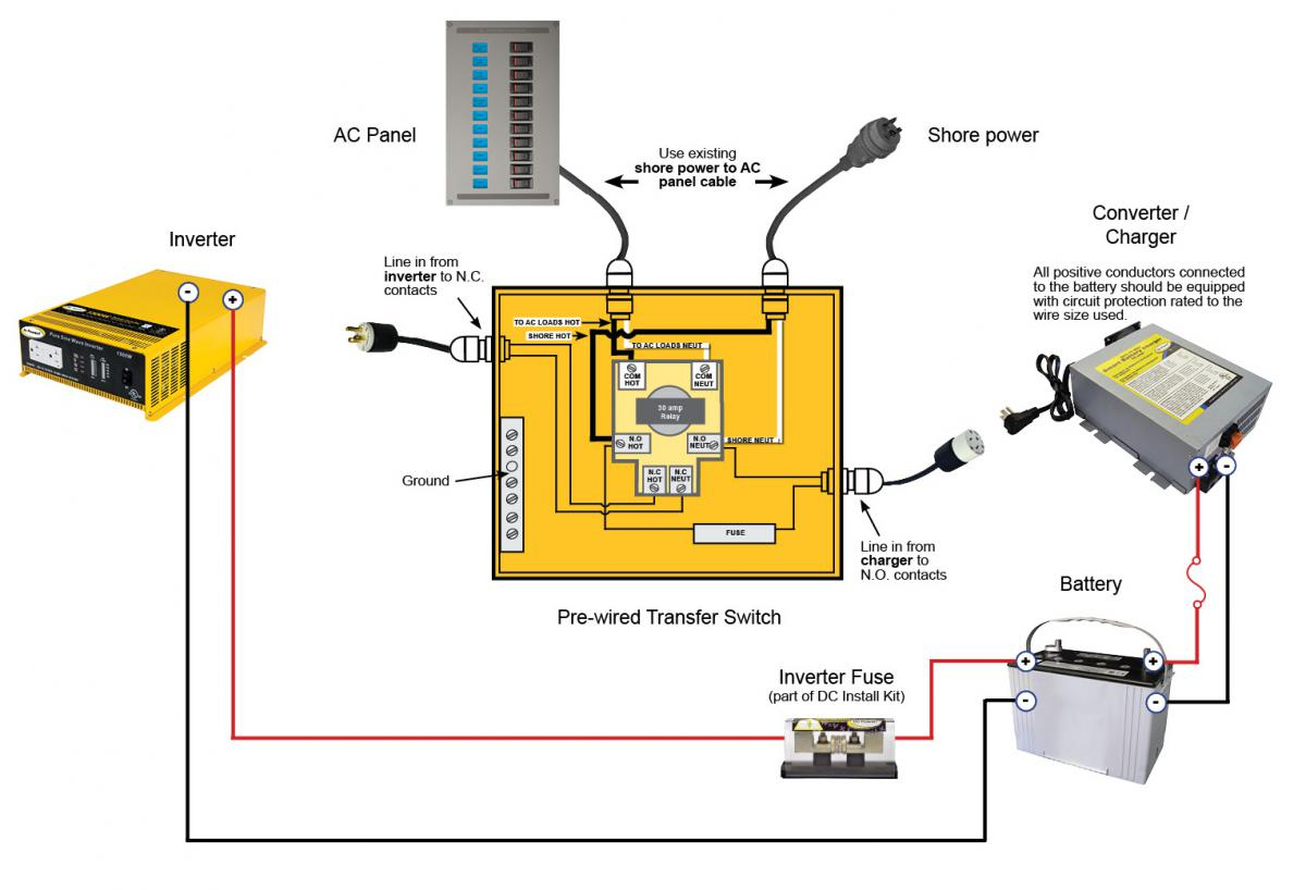
Rv Auto 50 Amp Transfer Switch Wiring Diagram Ts 30 wiring diagram . the ts 30 switches between two ac sources and only two sources. if three sources are on the rv, then two switches would be required. here are some examples of different ways to wire a ts 30 transfer switch. #1 ts #30 switching between shore power and generator #2 ts 30 between inverter and shore power. The bypass isolation ats control wiring diagram includes connections for the utility power, backup generators, bypass switch, load, and various control circuits for automatic transfer, bypass operation, and alarm monitoring. these are just a few of the main categories of automatic transfer switch control wiring diagrams. Disconnect from any shore power and generators and isolate your battery bank before you begin. step 1: identify your priority ac circuits. these will be powered by the inverter when you are off grid. step 2: install your inverter, with an ac distribution box with individual circuit rcds for each priority circuit. Wiring instructions warning: this automatic line generator switch is rated for use on circuits capable of delivering 105 130 vac 60 hz 30 aac. all field wires used have to be rated to at least 105 c. all grounds are connected inside of the t 30.: select a propper wire type, gage, and wire connector according to the nec requrements.

Wiring Diagram For 50 Amp Rv Service Disconnect from any shore power and generators and isolate your battery bank before you begin. step 1: identify your priority ac circuits. these will be powered by the inverter when you are off grid. step 2: install your inverter, with an ac distribution box with individual circuit rcds for each priority circuit. Wiring instructions warning: this automatic line generator switch is rated for use on circuits capable of delivering 105 130 vac 60 hz 30 aac. all field wires used have to be rated to at least 105 c. all grounds are connected inside of the t 30.: select a propper wire type, gage, and wire connector according to the nec requrements. An this is a pdf file of the schematic diagram and a pdf file of the wiring diagram. the wiring that runs your rv (and conveniently powers all the electrical gadgets that we love and need) is getting its energy from a huge electrical cord that is connected to a pedestal with outlets in the rv park. this plug is wired to a 120 volt breaker panel. The following will describe how to test for proper circuit board operation and how to replace it if necessary. 1. disconnect all ac power from the rv and make sure the generator is “off” 2. remove the cover from the ats. 3. with the power off check for 3k 7k ohms on the red and yellow wires to the relay.

Comments are closed.