Schematic Diagram Of Air Compressor

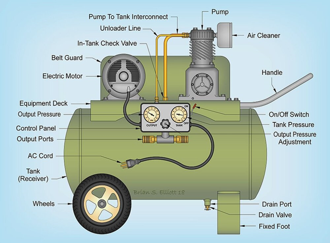
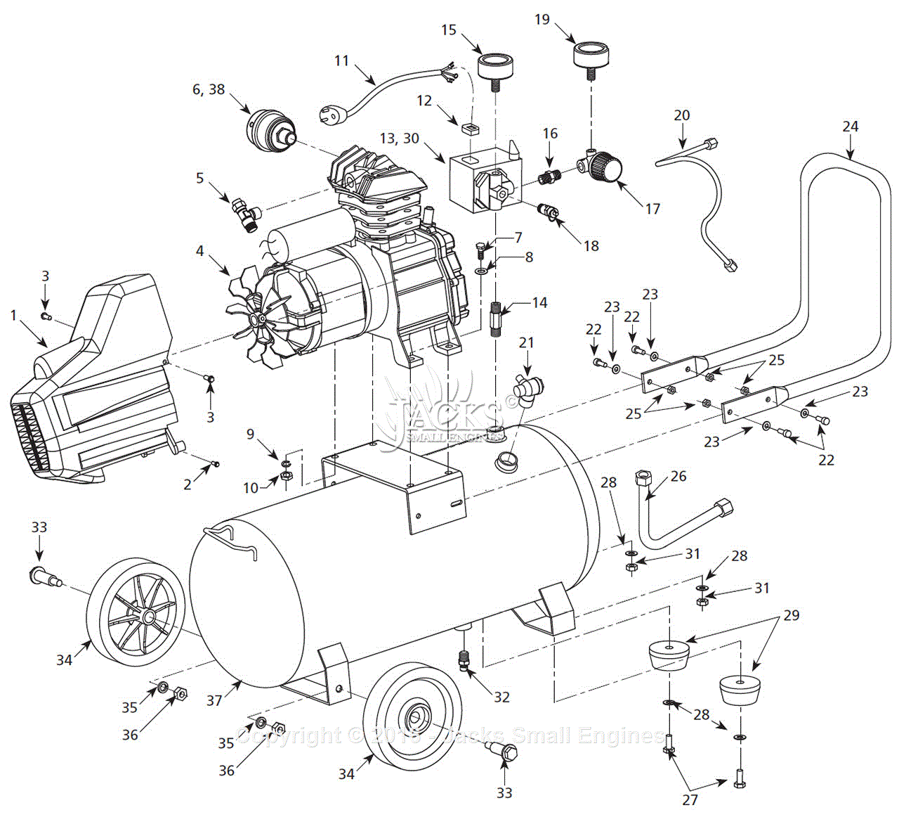
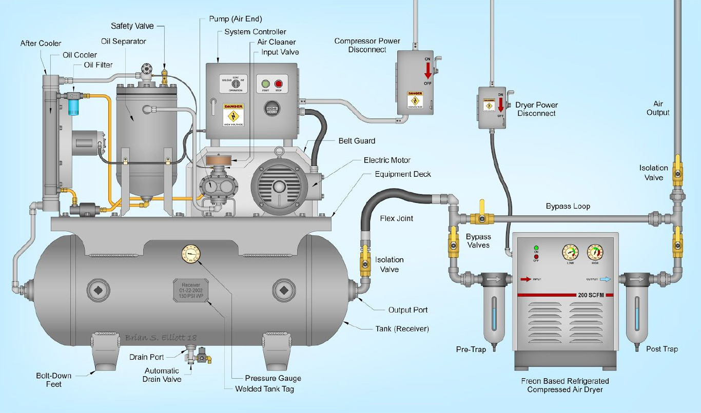
Schematic Diagram Of Air Compressor Air compressor anatomy 101. Air compressors consist of many components to ensure that your system provides high quality compressed air, and so, it can often be difficult to understand the role of each component. this article will provide you with a few annotated diagrams of air compressor systems, with descriptions about each part to follow.

Schematic Diagram Of Air Compressor Advantages of reciprocating compressor. 1. piston type compressors are available in a wide range of capacity and pressure. 2. very high air pressure (250 bar) and air volume flow rate is possible with multi staging. 3. better mechanical balancing is possible by a multistage compressor by proper cylinder arrangement. 4. The schematic diagram starts with the air compressor, which is the heart of the system. it takes in atmospheric air and compresses it to a higher pressure. the compressed air then flows into an air receiver tank, where it is stored and allows for a steady supply of compressed air to the system. Because the compressed air temperature out of the compressor is 10°c higher than the ambient tempera ture, the refrigerant dryer inlet temperature will be maximum 30 10 = 40°c. in addition, the desired pressure dew point is 5°c. the appropriate correction factor 0.95 is obtained from the atlas copco data sheet. The diagrams of how an air compressor works show that it has three main parts: a motor, a pump, and a tank. the motor powers the pump, which compresses air and stores it in the tank. when you need to use the air, the tank releases it through a hose or nozzle. the pump also has several subparts, including an intake valve, a piston, and a.

Schematic Diagram Of Air Compressor Because the compressed air temperature out of the compressor is 10°c higher than the ambient tempera ture, the refrigerant dryer inlet temperature will be maximum 30 10 = 40°c. in addition, the desired pressure dew point is 5°c. the appropriate correction factor 0.95 is obtained from the atlas copco data sheet. The diagrams of how an air compressor works show that it has three main parts: a motor, a pump, and a tank. the motor powers the pump, which compresses air and stores it in the tank. when you need to use the air, the tank releases it through a hose or nozzle. the pump also has several subparts, including an intake valve, a piston, and a. 1. air intake. the air intake is the first component in an air compressor flow diagram. it is responsible for drawing in ambient air and supplying it to the compressor for further processing. the air intake typically consists of a filter to remove impurities and ensure clean air is taken in. 2. Here are some common compressed air schematic symbols: 1. compressor. the compressor is the heart of a compressed air system and is represented by a circle with an arrow pointing towards it. the arrow indicates the direction of air flow into the compressor. 2. air receiver tank. the air receiver tank is used to store compressed air in a system.

Rotary Screw Air Compressor Basics Rasmussen Mechanical 1. air intake. the air intake is the first component in an air compressor flow diagram. it is responsible for drawing in ambient air and supplying it to the compressor for further processing. the air intake typically consists of a filter to remove impurities and ensure clean air is taken in. 2. Here are some common compressed air schematic symbols: 1. compressor. the compressor is the heart of a compressed air system and is represented by a circle with an arrow pointing towards it. the arrow indicates the direction of air flow into the compressor. 2. air receiver tank. the air receiver tank is used to store compressed air in a system.

Comments are closed.