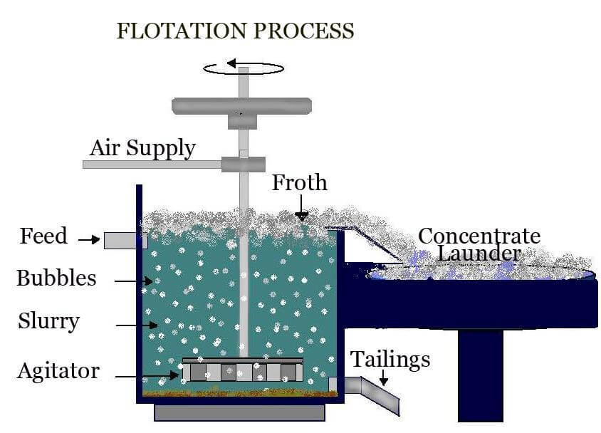
Schematic Illustration Of The Laboratory Froth Flotation Cell

Schematic Illustration Of The Laboratory Froth Flotation Cell Flotations were performed in a voith flotation cell (j.m. voith gmbh, heidenheim, germany), consisting of a plexiglas cube with a side length of 30 cm, at an impeller rotational speed of 1340 rpm. Figure 8 a schematic diagram of the bateman flotation cell (courtesy of bateman process equipment, south africa). from 5 m3 (bqr 50) to 100 m3(bqr 1000). the tank dimensions of different cells of varying sizes are given in table 1. the unit cell design bateman cells are called hiflo and hiclean machines.

Froth Flotation Process No flotation can occur. contact between particles and bubbles can be accomplished in a flotation cell such as the one shown schematically in figure 5. figure 5: simplified schematic of a conventional flotation cell. the rotor draws slurry through the stator and expels it to the sides, creating a suction that draws air down the shaft of the stator. Diagram of a cylindrical flotation cell with camera and light used in image analysis of the froth surface. froth flotation is a process for selectively separating hydrophobic materials from hydrophilic. this is used in mineral processing, paper recycling and waste water treatment industries. historically this was first used in the mining. Froth flotation is a physico chemical separation process. separation is principally based on differences in surface hydrophobicity. however, particle size and density have a significant impact. initial flotation patent and application was developed for graphite by the bessel brothers (1877). similar to graphite, coal is naturally hydrophobic. A laboratory flotation column using venturi aerators and a vacuum system to remove froth was used to investigate the contribution of gas flow, pulp flow, cell volume and froth retention time on.

The Schematic Froth Flotation Cell Download Scientific Diagram Froth flotation is a physico chemical separation process. separation is principally based on differences in surface hydrophobicity. however, particle size and density have a significant impact. initial flotation patent and application was developed for graphite by the bessel brothers (1877). similar to graphite, coal is naturally hydrophobic. A laboratory flotation column using venturi aerators and a vacuum system to remove froth was used to investigate the contribution of gas flow, pulp flow, cell volume and froth retention time on. The main principle of the froth flotation process depends on the differences in the wetting properties of the sulfide ore and the impurities (which may or may not be non sulfide ores). figure 1: froth flotation cell[4] the components of a flotation system are (figure 1): cell: a container that contains an impeller and is. Therefore, the aim of this study was to design and construct a 0.012 m 3 capacity laboratory froth flotation machine using locally sourced materials with the view to promoting indigenous.

Schematic Diagram Of A Continual Froth Flotation Separation Cell 1 The main principle of the froth flotation process depends on the differences in the wetting properties of the sulfide ore and the impurities (which may or may not be non sulfide ores). figure 1: froth flotation cell[4] the components of a flotation system are (figure 1): cell: a container that contains an impeller and is. Therefore, the aim of this study was to design and construct a 0.012 m 3 capacity laboratory froth flotation machine using locally sourced materials with the view to promoting indigenous.

Comments are closed.