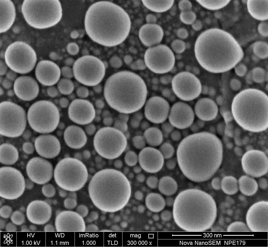
Sem Images Of A The As Fabricated 2 вµm Cu Ag And B 350 Nm Cu Particles

Sem Images Of A The As Fabricated 2 вµm Cu Ag And B 350 Download scientific diagram | sem images of a the as fabricated 2 µm cu@ag and b 350 nm cu particles. c cross sectional back scattered electron (bse) image of the 2 µm cu@ag particle from. Accordingly, the average size of the cu@ag particles increased slightly to 351 ± 161 nm after plating. fig. 2 (c) shows the xrd results of the cu@ag particles and the tem image of the cu core. although three crystallographic planes, (111), (200), and (220), were detected in the cu core, the peak intensity of the (111) plane was higher than.

The Highest Quality Premium Proxies Scanning Electron Microscope Pressure assisted die bonding at 250 °c in air using a paste containing 2 µm ag coated cu particles (cu@ag) and 350 nm cu particles was demonstrated for power device bonding. at a cu@ag to cu mixing ratio of 6:4, the sinter bonded dies showed a considerable average shear strength that approached 25 mpa after only 5 min of bonding. furthermore, a near full density bondline and excellent. Sinter bonding characteristics were examined using pastes containing surface modified submicron cu@ag particles. sinter bonding was conducted at 250 °c under 10 mpa for 1–10 min with n 2 blowing using eight types of initial and surface modified submicron cu@ag particles with ag contents of 10, 20, 30, and 40 wt% (a10, a20, a30, and a40). the. The fabricated [email protected] particles were spherical with the average size of 2 μm, and the ag shell was 250–400 nm in thickness, comprising a mixed ag cu layer and a dense ag layer. Sem images and corresponding eds results for the as quenched cu–ag alloys: (a) cu–10ag, (b) high magnification image of cu–10ag, (c) cu–15ag, and (d) high magnification image of cu–15ag a more detailed analysis of the microstructure of the as quenched cu–10ag was performed using ebsd and tem, as shown in fig. 4 .

Sem Images Electron Nanoscopy Instrumentation Facility The fabricated [email protected] particles were spherical with the average size of 2 μm, and the ag shell was 250–400 nm in thickness, comprising a mixed ag cu layer and a dense ag layer. Sem images and corresponding eds results for the as quenched cu–ag alloys: (a) cu–10ag, (b) high magnification image of cu–10ag, (c) cu–15ag, and (d) high magnification image of cu–15ag a more detailed analysis of the microstructure of the as quenched cu–10ag was performed using ebsd and tem, as shown in fig. 4 . For the application of as prepared cu@ag nps as printed electronics, the coated nps film was prepared by the same as the previous work []. pastes containing the fabricated cu@ag nps were heated to 220°c in a vacuum (50 mtorr). figs. 3b and c show the scanning electron microscopy (sem) images of the conductive ink before and after sintering. it. A sem image b tem image of sample 1 (with ag contents 27.93 wt%) c tem image of sample 2 (with ag contents 14.69 wt%) d tem image of sample 3 (with ag contents 7.68 wt%) e eds line scanning of the intermediates f eds line scanning of a spherical cu@ag core–shell nanoparticle micro & nano letters, 2018, vol. 13, iss. 2, pp. 171–174.

Sem Image Of A Snowflake Like Znco2o4 Zno Microstructures 99 Tem For the application of as prepared cu@ag nps as printed electronics, the coated nps film was prepared by the same as the previous work []. pastes containing the fabricated cu@ag nps were heated to 220°c in a vacuum (50 mtorr). figs. 3b and c show the scanning electron microscopy (sem) images of the conductive ink before and after sintering. it. A sem image b tem image of sample 1 (with ag contents 27.93 wt%) c tem image of sample 2 (with ag contents 14.69 wt%) d tem image of sample 3 (with ag contents 7.68 wt%) e eds line scanning of the intermediates f eds line scanning of a spherical cu@ag core–shell nanoparticle micro & nano letters, 2018, vol. 13, iss. 2, pp. 171–174.

Comments are closed.