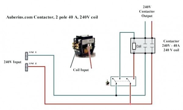
Single Phase 240 Volt Contactor Wiring Diagram

Single Phase 240 Volt Contactor Wiring Diagram The wiring diagram below uses a single phase contactor to reverse the direction of a single phase motor. single phase motor reversing circuit. working principle of reverse circuit: when the forward switch is turned on, contactor k1 is powered. capacitor in series with coil 2 and connected to power supply (n). How to wire a contactor single phase.first let's start with the common question what is a contactor?a contactor is an electrically controlled switch used for.

Single Phase 240 Volt Contactor Wiring Diagram Route the wires. remove all power to the wires. run all input and output wires to the contactor. these wires should be rated in the manufacturer information. use wire strippers to cut excess length off of the ends of the wire, making sure that the wires are long enough to reach the intended contact. A single phase motor is an electrically powered rotary machine that can turn electric energy into mechanical energy. it works by using a single phase power s. The main components in a single phase motor contactor wiring diagram include the contactor itself, overload relay, auxiliary contact, power supply, and motor. the contactor is the central device that controls the switching of power to the motor. it consists of a coil, contacts, and an auxiliary contact that is used for control purposes. To wire a single phase magnetic contactor, follow the steps below: disconnect the power supply to the circuit to ensure safety. connect the incoming power line to the power terminals of the contactor. connect one end of the control switch or push button to the control terminal of the contactor.

Single Phase Contactor Wiring Diagram Everything You Need To Know The main components in a single phase motor contactor wiring diagram include the contactor itself, overload relay, auxiliary contact, power supply, and motor. the contactor is the central device that controls the switching of power to the motor. it consists of a coil, contacts, and an auxiliary contact that is used for control purposes. To wire a single phase magnetic contactor, follow the steps below: disconnect the power supply to the circuit to ensure safety. connect the incoming power line to the power terminals of the contactor. connect one end of the control switch or push button to the control terminal of the contactor. A contactor wiring diagram is a visual representation of the electrical connections and components of a contactor. it provides a detailed outline of how the contactor is wired and how it operates in an electrical circuit. understanding the basics of a contactor wiring diagram is essential for anyone working with contactors or troubleshooting. The above diagram is a complete method of single phase motor wiring with a circuit breaker and contactor. in the above one phase motor wiring i first connect a 2 pole circuit breaker and after that, i connect the supply to the motor starter then i do cont actor coil wiring with normally close push button switch and normally open push button.

Comments are closed.