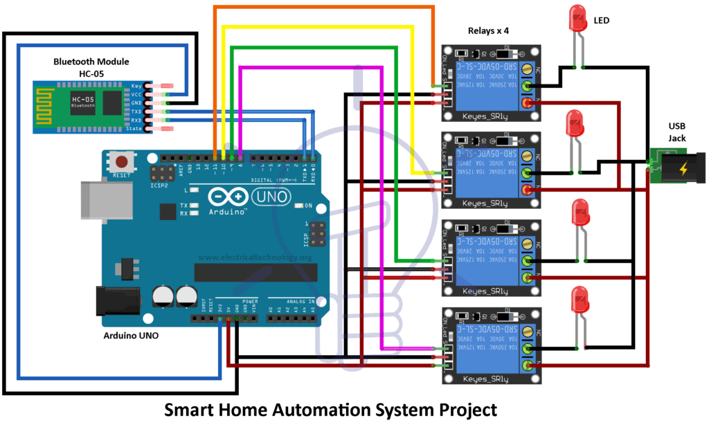
Smart Home Automation System Project Source Code And Circuit

Smart Home Automation System Project Source Code And Circuit Make the connection for home automation project as given in the circuit diagram. first of all, we connect the bulb with ac powered sources and with relays as given in the circuit diagram. then the relays are given dc power from the arduino uno board. data pins of the relays are connected at pins 8, 9, 10 and 11 to the arduino which are the. Below is a list of some home automation projects which are based on various microcontrollers, arduino, raspberry pi, etc. these home automation projects are covered with detailed explanation of circuit diagrams, source codes and videos. february 14, 2024.

Smart Home Automation System Project Source Code And Circuit вђ Artofit 1. install the blynk app from the google play store or app store. then create an account and tap on the new project. 2. give the name to the project, select esp32 dev board, connection type will be wifi. then tap on create. 3. blynk will send an authentication token to the registered email id. tap on ok. This is the complete circuit diagram for this home automation project. i have explained the circuit in the tutorial video. the circuit is very simple, i have used the gpio pins d1, d2, d5 & d6 to control the 4 relays. and the gpio pins sd3, d3, d7 & rx are connected with push buttons to control the 4 relays manually. Step 1: connecting the components. begin by connecting the relay module with the arduino uno board. connect the vcc pin of the relay module to the 5v pin on the arduino board, and connect the gnd. This is the complete circuit diagram for this home automation project. i have explained the circuit in the tutorial video. the circuit is very simple, i have used the gpio pins d1, d2, d5 & d6 to control the 4 relays. and the gpio pins sd3, d3, d7 & rx connected with push buttons to control the 4 relays manually.

Comments are closed.