Solved Draw Shear Force And Bending Moment Diagram For The

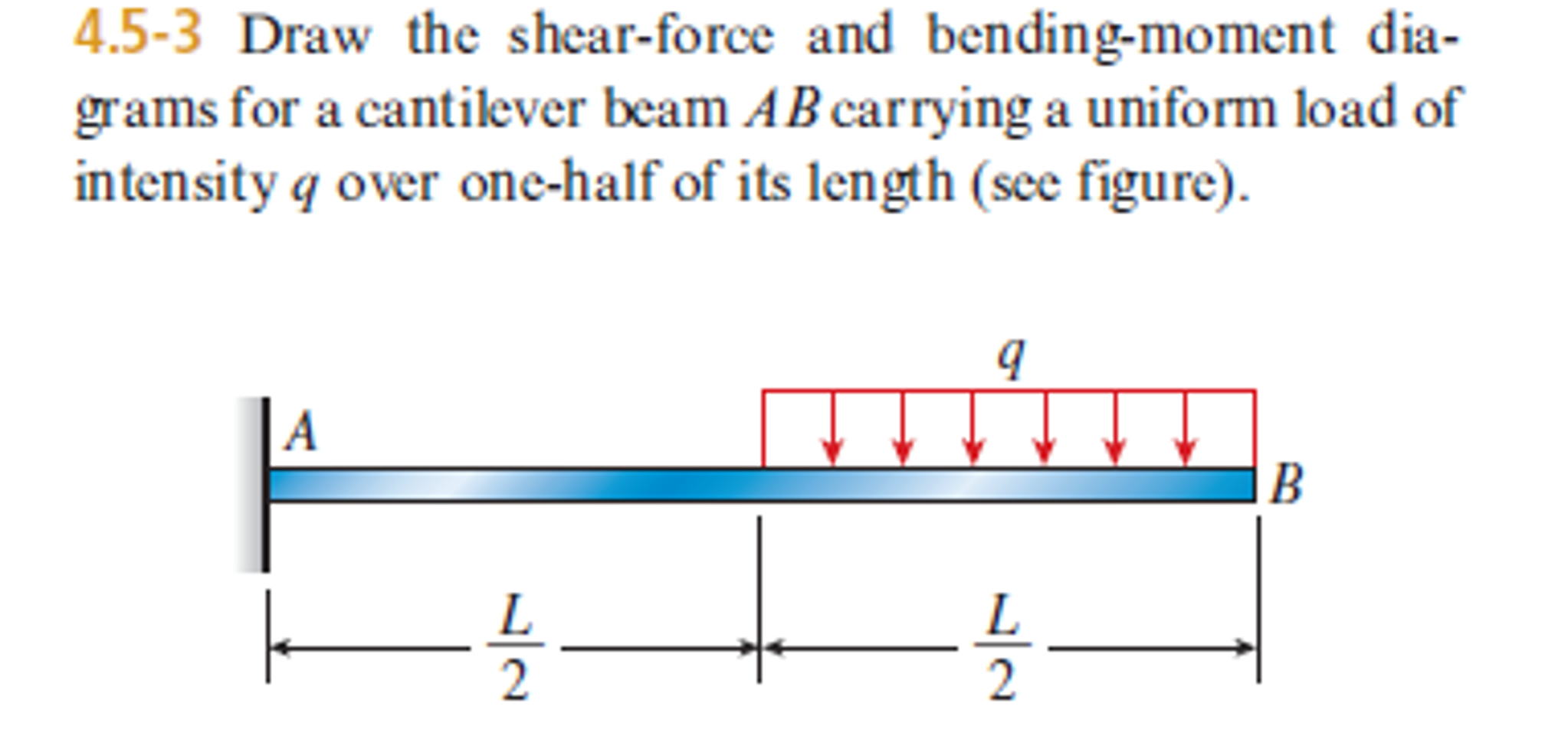
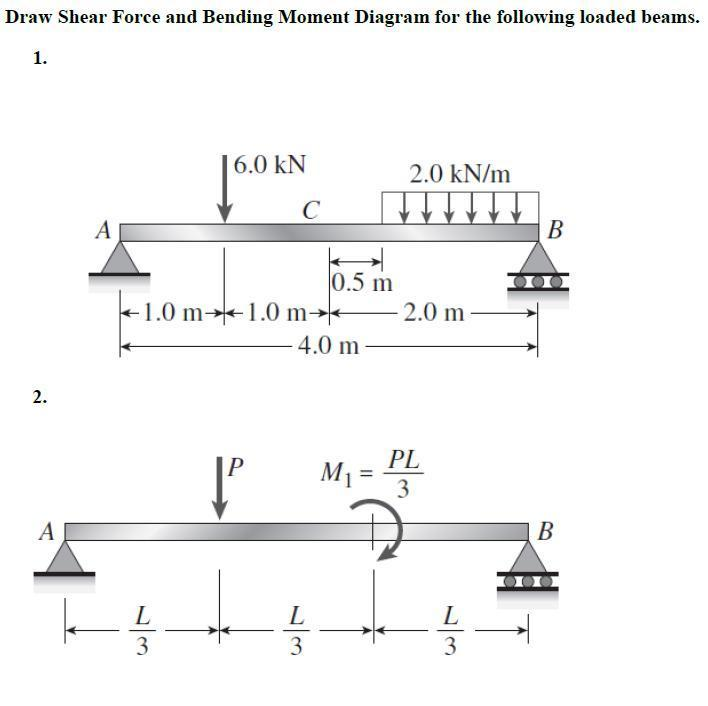
Solved Draw The Shear Force And Bending Moment Diagrams Fo Being able to draw shear force diagrams (sfd) and bending moment diagrams (bmd) is a critical skill for any student studying statics, mechanics of materials, or structural engineering. there is a long way and a quick way to do them. Draw the shear force and bending moment diagram for the following beam structure under external loads. your solution’s ready to go! our expert help has broken down your problem into an easy to learn solution you can count on.

Solved Draw Shear Force And Bending Moment Diagram For The Chegg Draw the shear force and bending moment diagrams for the cantilever beam supporting a concentrated load of 5 lb at the free end 3 ft from the wall. 1. draw a fbd of the structure . 2. calculate the reactions using the equilibrium equations (may not need to do this if choosing a cantilever beam and using the free side for the fbd). A bending moment diagram is a graphical representation of the bending moment forces along a structural member, such as a beam. the diagram shows the values of the bending moment along the length of the beam. the bending moment is a measure of the bending force in a beam and is calculated by multiplying the load by the distance from the neutral. Learn to draw shear force and moment diagrams using 2 methods, step by step. we go through breaking a beam into segments, and then we learn about the relatio. Draw the shear force and bending moment diagrams for the cantilever beam supporting a concentrated load of 5 lb at the free end 3 ft from the wall. 1. draw a fbd of the structure . 2. calculate the reactions using the equilibrium equations (may not need to do this if choosing a cantilever beam and using the free side for the fbd).

Solved Draw The Shear Force And Bending Moment Diagrams Learn to draw shear force and moment diagrams using 2 methods, step by step. we go through breaking a beam into segments, and then we learn about the relatio. Draw the shear force and bending moment diagrams for the cantilever beam supporting a concentrated load of 5 lb at the free end 3 ft from the wall. 1. draw a fbd of the structure . 2. calculate the reactions using the equilibrium equations (may not need to do this if choosing a cantilever beam and using the free side for the fbd). Plots of v(x) v ( x) and m(x) m ( x) are known as shear and bending moment diagrams, and it is necessary to obtain them before the stresses can be determined. for the end loaded cantilever, the diagrams shown in figure 3 are obvious from eqns. 4.1.1 and 4.1.2. figure 4: wall reactions for the cantilevered beam. Mechanical engineering questions and answers. draw the shear force and bending moment diagrams for the beam shown in fig q3. the forces p1 and p2 are 36 and 70 kn respectively and the dimensions e, f and g are 0.3, 0.5 and 0.2 m respectively. the beam has a rectangular cross section with breadth b = 140 mm and depth d = 240 mm, calculate the.

Shear And Bending Moment Diagrams Examples Plots of v(x) v ( x) and m(x) m ( x) are known as shear and bending moment diagrams, and it is necessary to obtain them before the stresses can be determined. for the end loaded cantilever, the diagrams shown in figure 3 are obvious from eqns. 4.1.1 and 4.1.2. figure 4: wall reactions for the cantilevered beam. Mechanical engineering questions and answers. draw the shear force and bending moment diagrams for the beam shown in fig q3. the forces p1 and p2 are 36 and 70 kn respectively and the dimensions e, f and g are 0.3, 0.5 and 0.2 m respectively. the beam has a rectangular cross section with breadth b = 140 mm and depth d = 240 mm, calculate the.

Comments are closed.