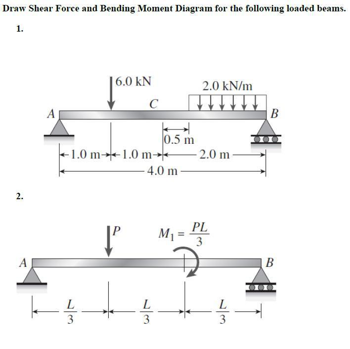
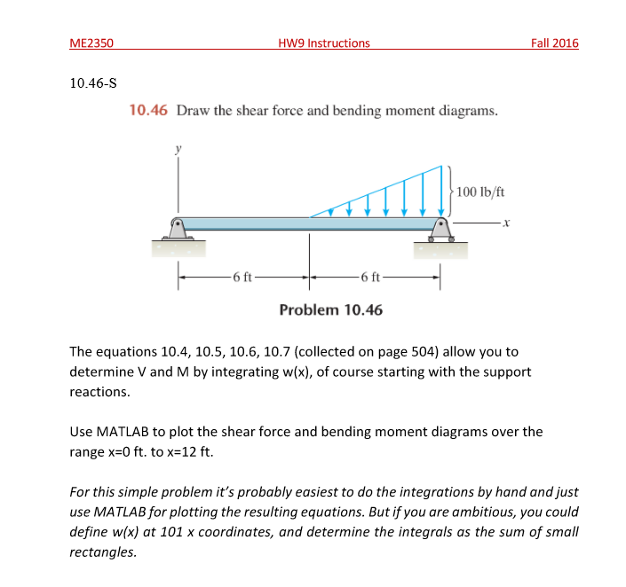
Solved Draw Shear Force And Bending Moment Diagrams For Th

Solved Draw Shear Force And Bending Moment Diagram For Draw th shear force and bending moment diagrams for the beam shown below 20kn m 20kn 5kn 4m 2m 2m4m 3m your solution’s ready to go! our expert help has broken down your problem into an easy to learn solution you can count on. Draw the shear force and bending moment diagrams for the cantilever beam supporting a concentrated load of 5 lb at the free end 3 ft from the wall. 1. draw a fbd of the structure . 2. calculate the reactions using the equilibrium equations (may not need to do this if choosing a cantilever beam and using the free side for the fbd).

Solved Draw The Shear Force And Bending Moment Diagrams Ch Being able to draw shear force diagrams (sfd) and bending moment diagrams (bmd) is a critical skill for any student studying statics, mechanics of materials, or structural engineering. there is a long way and a quick way to do them. Plots of v(x) v ( x) and m(x) m ( x) are known as shear and bending moment diagrams, and it is necessary to obtain them before the stresses can be determined. for the end loaded cantilever, the diagrams shown in figure 3 are obvious from eqns. 4.1.1 and 4.1.2. figure 4: wall reactions for the cantilevered beam. 72. lecture 1 4:shear force and bending moment. concept of shear force and bending moment in beams: when the beam is loaded in some arbitrarily manner, the internal forces and moments are developed and the terms shear force and bending moments come into pictures which are helpful to analyze the beams further. let us define these terms. 5.0 drawing shear force and bending moment diagrams – an example. now that we have a grasp of the fundamentals, let’s see how it all ties together with a bigger more complex worked example. this example is an extract from this course. just a quick heads up, if you’re new to shear force and bending moment diagrams, this question might be a.

Solved Draw The Shear Force And Bending Moment Diagrams 72. lecture 1 4:shear force and bending moment. concept of shear force and bending moment in beams: when the beam is loaded in some arbitrarily manner, the internal forces and moments are developed and the terms shear force and bending moments come into pictures which are helpful to analyze the beams further. let us define these terms. 5.0 drawing shear force and bending moment diagrams – an example. now that we have a grasp of the fundamentals, let’s see how it all ties together with a bigger more complex worked example. this example is an extract from this course. just a quick heads up, if you’re new to shear force and bending moment diagrams, this question might be a. Question: draw the shear and bending moment diagrams for the beam and loading shown, and determine the maximum absolute value of (a) the shear (b) the bending moment. draw the shear and bending moment diagrams for the beam and loading shown, and determine the maximum absolute value of. there are 2 steps to solve this one. Shear and moment diagrams are graphs which show the internal shear and bending moment plotted along the length of the beam. they allow us to see where the maximum loads occur so that we can optimize the design to prevent failures and reduce the overall weight and cost of the structure. since beams primarily support vertical loads the axial.
Solved 1 Draw The Bending Moment And Shear Force Diagrams Question: draw the shear and bending moment diagrams for the beam and loading shown, and determine the maximum absolute value of (a) the shear (b) the bending moment. draw the shear and bending moment diagrams for the beam and loading shown, and determine the maximum absolute value of. there are 2 steps to solve this one. Shear and moment diagrams are graphs which show the internal shear and bending moment plotted along the length of the beam. they allow us to see where the maximum loads occur so that we can optimize the design to prevent failures and reduce the overall weight and cost of the structure. since beams primarily support vertical loads the axial.

Solved Draw The Shear Force And Bending Moment Diagrams Of

Comments are closed.