Star Connection In A 3 Phase System Relation Between Phase Line

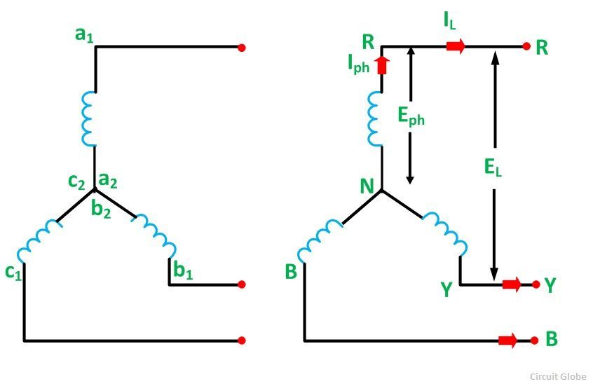
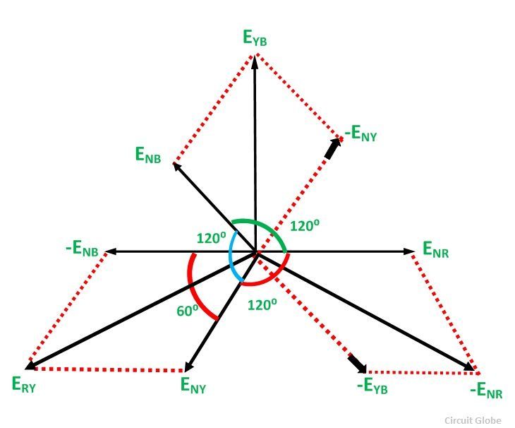
Star Connection In A 3 Phase System Relation Between Phase Line Hence, in star connection line voltage is root 3 times of phase voltage. relation between phase current and line current in star connection. the same current flows through phase winding as well as in the line conductor as it is connected in series with the phase winding. where the phase current will be: the line current will be: hence, in a 3. P = √3 x vl x il x cosФ. the same is explained in 3 phase circuit mcqs with explanatory answer (mcqs no.1) similarly, total reactive power = q = √3 x vl x il x sinФ. where cos Φ = power factor = the phase angle between phase voltage and phase current and not between line current and line voltage.

Star Connection In A 3 Phase System Relation Between Phase Line Star connected system definition: a star connected system is a type of electrical circuit where each component connects to a common neutral point. voltage relationship: in a star connected system, the line voltage is √3 times the phase voltage. current relationship: the line current is the same as the phase current in a star connected system. When there are three lines carrying three phase electricity, the voltage between every two lines is called line to line or simply line voltage. in the presence of a fourth line, the voltage between each line and the common point (or the null line) is called phase voltage. this is irrespective of how the connection is at the source. Typically, the rms phase voltage is 230 or 240 v. whereas the rms line voltage is 415 v or 440 v and the frequency of phase and line voltages is 50 hz. thus in the star connected system the line voltage is higher than the phase voltage by a factor \(\sqrt{3}\text{ }\). \[\text{line voltage = }\sqrt{3}\text{ phase voltage }\] and. Consequently, if the load is leading, then the angle between the line (phase) current and corresponding line voltage will be (30 — Φ)°. the total active power or true power in the three phase load is the sum of the powers in the three phases. for a balanced load, the power in each load is the same; hence total power = 3 x power in each phase.

Star Connection In A 3 Phase System Relation Between Phase Line Typically, the rms phase voltage is 230 or 240 v. whereas the rms line voltage is 415 v or 440 v and the frequency of phase and line voltages is 50 hz. thus in the star connected system the line voltage is higher than the phase voltage by a factor \(\sqrt{3}\text{ }\). \[\text{line voltage = }\sqrt{3}\text{ phase voltage }\] and. Consequently, if the load is leading, then the angle between the line (phase) current and corresponding line voltage will be (30 — Φ)°. the total active power or true power in the three phase load is the sum of the powers in the three phases. for a balanced load, the power in each load is the same; hence total power = 3 x power in each phase. The term y y applies since both the source and the load are y connected. the system is said to be balanced since the source voltages constitute a balanced set and the load is balanced (each phase impedance zp is equal). the fourth wire is the neutral line n n, which may be omitted to form a three phase, three wire system. Star connection or y connection is an arrangement of three of same or different passive components (resistor, inductor, capacitor). this arrangement is generally used in the three phase power system to deliver the balanced load from the alternating current (ac) voltage source. when the current flow through all three phases is equal then it is.

Phasor Diagram 3 Phase Star Connection The term y y applies since both the source and the load are y connected. the system is said to be balanced since the source voltages constitute a balanced set and the load is balanced (each phase impedance zp is equal). the fourth wire is the neutral line n n, which may be omitted to form a three phase, three wire system. Star connection or y connection is an arrangement of three of same or different passive components (resistor, inductor, capacitor). this arrangement is generally used in the three phase power system to deliver the balanced load from the alternating current (ac) voltage source. when the current flow through all three phases is equal then it is.

Comments are closed.