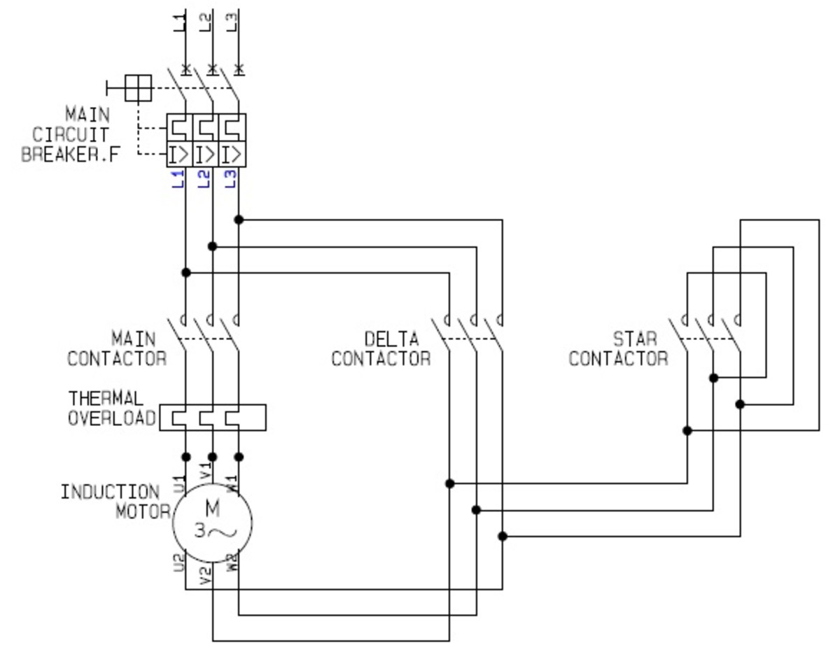
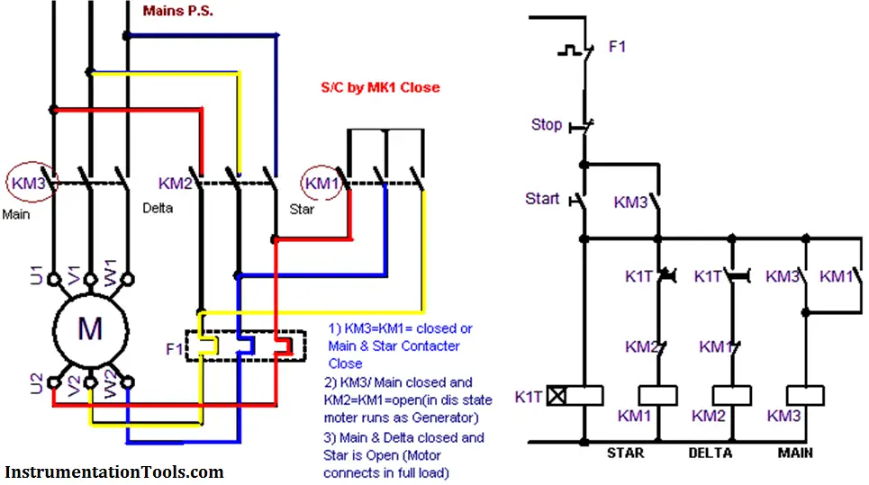
Star Delta Control Diagram With Motor Power Connection

Using Star Delta Motor Control With Circuit Diagrams Hubpages In this tutorial, we will demonstrate the automatic star delta (y Δ) starting method for 3 phase ac induction motors. this will include providing a schematic, power and control, plc ladder, and wiring diagrams. we will also explain how the star delta starter works and discuss its applications, as well as its advantages and disadvantages. The wiring diagram for a 132kw star delta starter used for a condenser pump is shown below: star delta starter wiring diagram. the diagram can be divided into two parts: the power circuit & control circuit.

Using Star Delta Motor Control With Circuit Diagrams Turbofuture In this video, you will learn the star delta motor starter with animation.the power and control circuit diagram of the electrical star and delta starter.star. The manual control procedure for the star delta starter without timer is relatively simple. it involves the following steps: initial state: the motor is at rest, and the windings are disconnected. star connection: press the “start” button or close the start contactor. this connects the motor windings in a star configuration. In the diagram of power circuit of star delta starter, u2 and v2 of 3 phase motor should be connect to 4 and 6 respectively instead of u2 and v2 are connected to 6 and 4 of delta contector km2. there is minor correction is require to change (printed in boxes) sequence of 3 phase wires from w2 v2 u2 to w2 u2 v2 to get delta connection properly. Principle of working of star delta starter. the motor is first started by connecting its stator winding in a star configuration. the phase voltage in the star configuration is 1 √ 3 of the phase to phase or line voltage. thus, the voltage applied to the stator winding is about 58 % of the line voltage. the starting stator current reduces to.

Circuit Diagram Star Delta Motor Connection In the diagram of power circuit of star delta starter, u2 and v2 of 3 phase motor should be connect to 4 and 6 respectively instead of u2 and v2 are connected to 6 and 4 of delta contector km2. there is minor correction is require to change (printed in boxes) sequence of 3 phase wires from w2 v2 u2 to w2 u2 v2 to get delta connection properly. Principle of working of star delta starter. the motor is first started by connecting its stator winding in a star configuration. the phase voltage in the star configuration is 1 √ 3 of the phase to phase or line voltage. thus, the voltage applied to the stator winding is about 58 % of the line voltage. the starting stator current reduces to. The typical star delta control circuit wiring diagram in the cad drawing below will help you follow the explanation. the star delta control circuit illustrated above actuates magnetic contactors that interchangeably execute star delta motor connections. pushing the on switch causes the motor to start running from the star connection to the. The key components of a star delta control diagram include: 1. timer. a timer is an essential component of a star delta control diagram. it controls the duration of the star connection and provides a delayed transition to the delta connection. the timer is typically set to a specific time, allowing the motor to start in star mode for a.

Star Delta Control Diagram With Motor Power Connection The typical star delta control circuit wiring diagram in the cad drawing below will help you follow the explanation. the star delta control circuit illustrated above actuates magnetic contactors that interchangeably execute star delta motor connections. pushing the on switch causes the motor to start running from the star connection to the. The key components of a star delta control diagram include: 1. timer. a timer is an essential component of a star delta control diagram. it controls the duration of the star connection and provides a delayed transition to the delta connection. the timer is typically set to a specific time, allowing the motor to start in star mode for a.

Dol And Star Delta Starter Circuit Diagram

Comments are closed.