Start Stop Jog Circuit Motor Control Circuit Diagram Electrical A2z

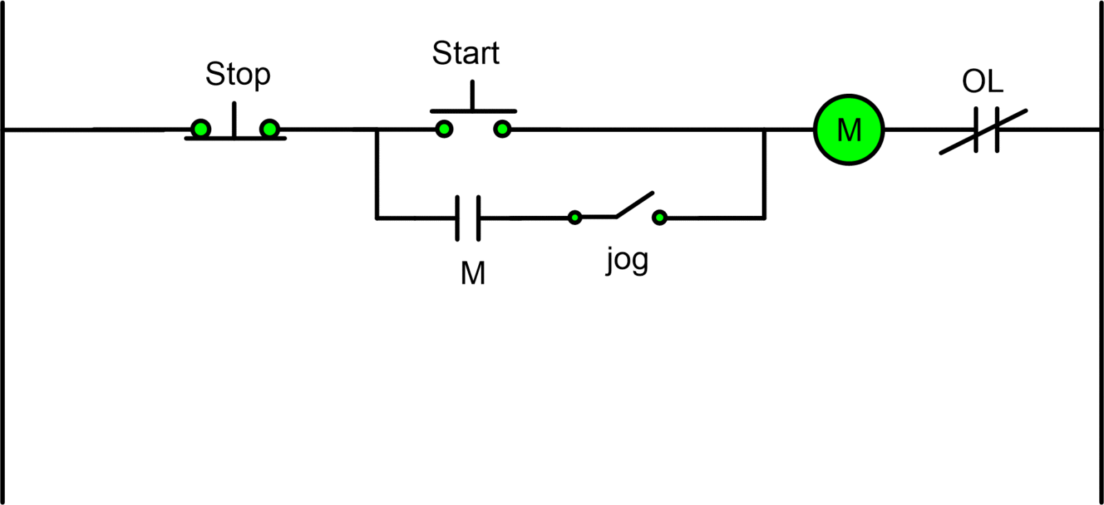
Start Stop Jog Circuit Motor Control Circuit Diagram Electrical A2z Jog circuit. the jog circuit in configuration 1 operates as follows: a switch is wired in series with the seal in of the pilot device. with the switch closed the control circuit acts as a normal stop start station controlling a load connected to the pilot device, power is sitting on the start and seal in terminals of the pushbutton. The diagram below illustrates the control circuit needed to accomplish the operation. first, the stop pushbuttons are connected in series to form a nor logic. next, the start pushbuttons are connected in parallel to form an or logic circuit. this control circuit is a variation of the three wire control circuit. configuration 4.

Start Stop Jog Circuit Motor Control Circuit Diagram Electrical A2z The diagram of a typical start stop motor control circuit shows us how to create a system that functions efficiently and safely. in this diagram, the green lines indicate the connection of a power source to the motor and the electric switch. when the switch is in the "on" position, the electric current travels from the power source, through the. Vfd start stop wiring diagram electrical4u. how to convert a basic wiring diagram plc program realpars. elte131 motor control and jogging diagram quizlet. maintenance basic controls model 8036 e. motor starter control circuit diagram electrical a2z. solved refer to the circuit shown in figure 10 8 this chegg com. jogging inching control. The motor control diagram start stop typically consists of various components, including a power supply, motor, start button, stop button, control relay, overload relay, and a fuse or circuit breaker. these components are interconnected using wires and connectors to create a circuit that controls the operation of the motor. The control circuit (start stop) tells a motor or electrical component when to run and stop. start stop circuits consist of a number of electrical components and wiring. the circuit itself will combine contacts, relays or contactors, overloads, electrical motors, and buttons to create an electrical circuit that will control the operation of a.

Start Stop Jog Motor Control Diagram The motor control diagram start stop typically consists of various components, including a power supply, motor, start button, stop button, control relay, overload relay, and a fuse or circuit breaker. these components are interconnected using wires and connectors to create a circuit that controls the operation of the motor. The control circuit (start stop) tells a motor or electrical component when to run and stop. start stop circuits consist of a number of electrical components and wiring. the circuit itself will combine contacts, relays or contactors, overloads, electrical motors, and buttons to create an electrical circuit that will control the operation of a. A simple start stop motor control circuit is composed of several key elements, including contactors, overload relays, motors, switches, and pilot devices. each of these components plays a crucial role in allowing the entire system to operate efficiently. contactors, for example, act as the main switching device in the circuit. 35 jog circuits . sometimes called “inching,” jogging is the term given to the momentary energization of a motor only so long as an operator is pressing a button. a jog circuit is a circuit that allows an operator to either start the motor or “jog” the motor and are commonly used for motors controlling conveyor belts to allow for precise positioning of materials.
Start Stop Jog Wiring Diagram A simple start stop motor control circuit is composed of several key elements, including contactors, overload relays, motors, switches, and pilot devices. each of these components plays a crucial role in allowing the entire system to operate efficiently. contactors, for example, act as the main switching device in the circuit. 35 jog circuits . sometimes called “inching,” jogging is the term given to the momentary energization of a motor only so long as an operator is pressing a button. a jog circuit is a circuit that allows an operator to either start the motor or “jog” the motor and are commonly used for motors controlling conveyor belts to allow for precise positioning of materials.

Comments are closed.