Tda2030 2 1 Amplifier Board Subwoofer Circuit Diagram Xtronic

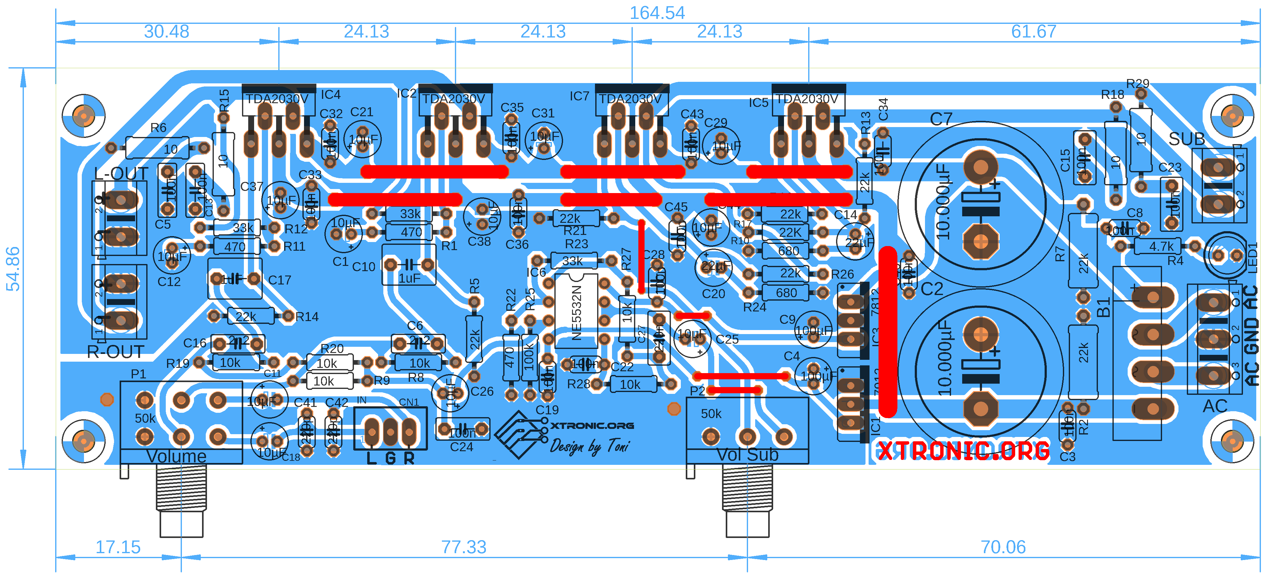
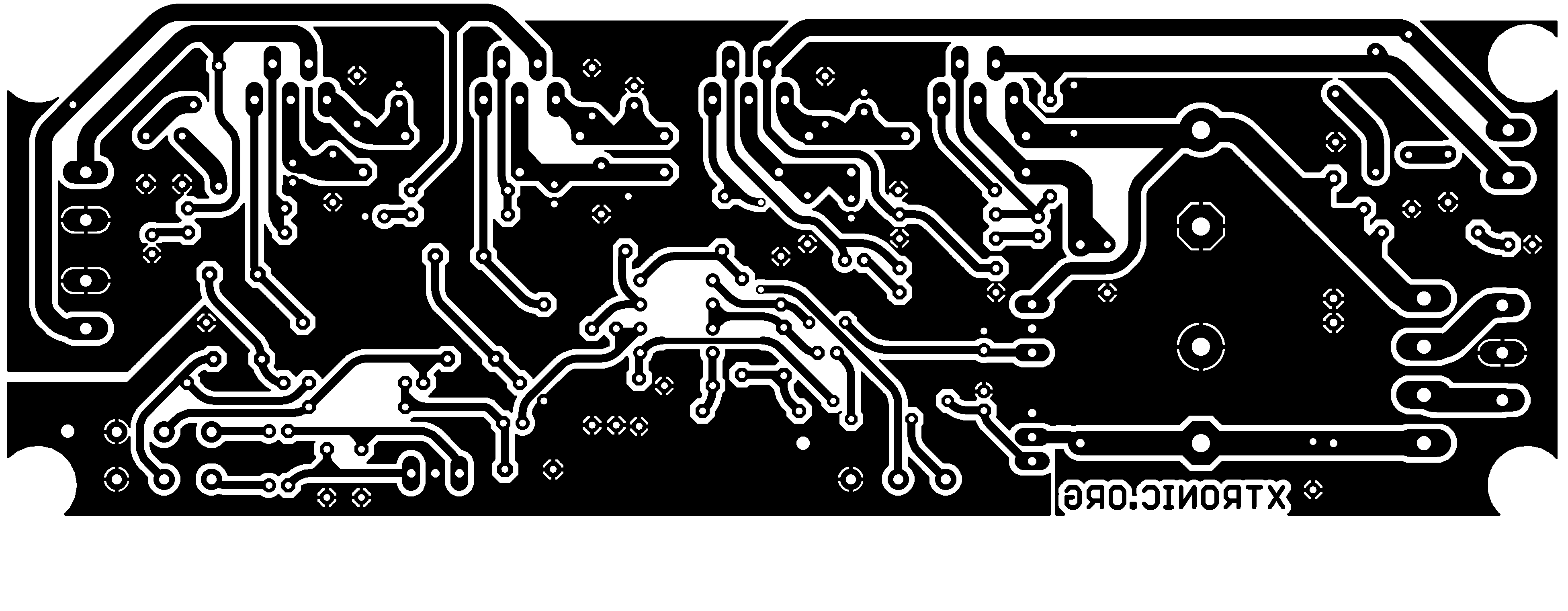
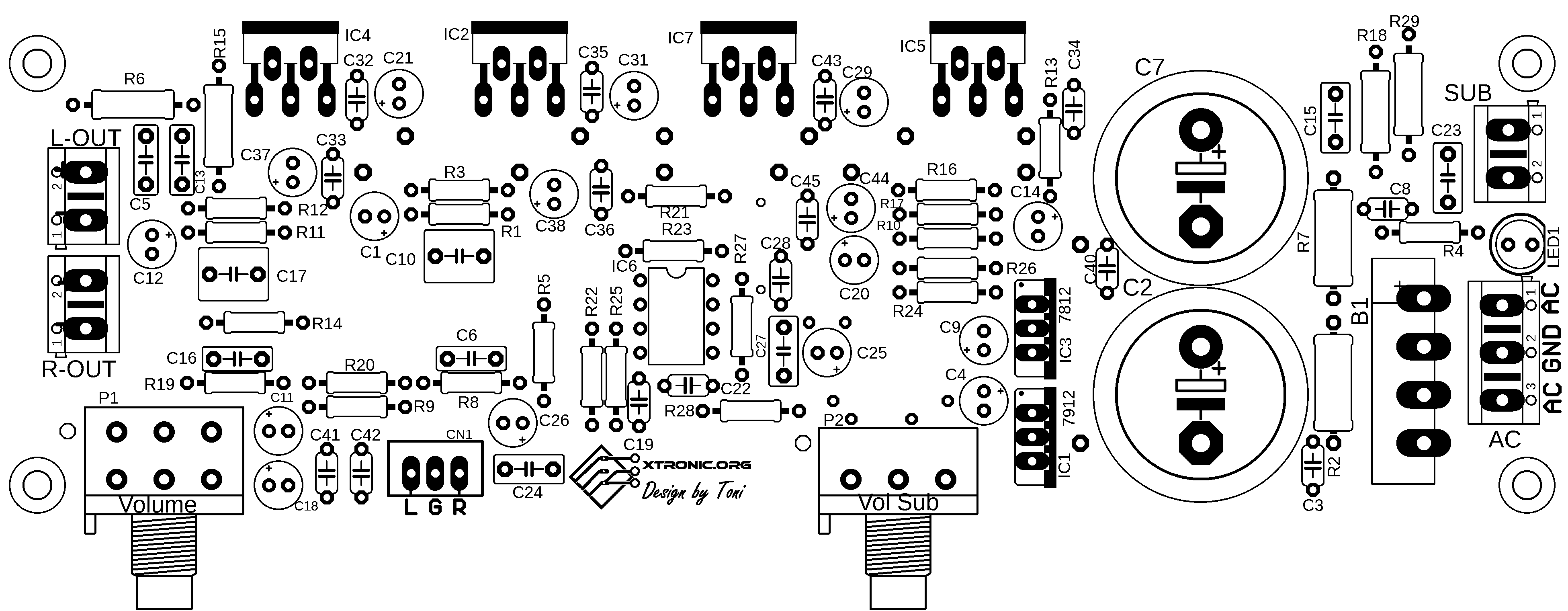
Tda2030 2 1 Amplifier Board Subwoofer Circuit Diagramођ Bom for assembling the power amplifier with subwoofer using tda2030 and ne5532. tda2030 2.1 amplifier board subwoofer circuit diagram. this circuit is typical of systems sold for 2.1 pc surround systems, left and right channel and subwoofer. just plugging in the stereo audio and adjust the volume. audio amplifier circuit using integrated. The circuit is divided into 3 parts: power supply, stereo amplifier and bass amplifier (subwoofer). tda2030 2.1 amplifier board circuit diagram subwoofer. this circuit is a complete application is 2.1 amp, two satellite speakers for tda2030 and one for the subwoofer, the 2.1 system, widely used in commercial applications as an amplifier for.

Tda2030 2 1 Amplifier Board Subwoofer Circuit Diagramођ Tda2030 amplifier circuit board diagram. tda2030 is a circuit integrated monolithic in pentawat® package, to be used as class audio amplifier ab. typically, he supplies up to 14 watts of potency (d=0.5%) @ 14v 4 Ω. the guaranteed potency is 12w in a load of 4 Ω and 8 watts in a load of 8 Ω. integrated him it bills with circuits of component. Power output: the tda2030 can provide a maximum power output of 14 watts, making it ideal for small to medium sized subwoofers. this power output ensures that the subwoofer can reproduce low frequencies accurately and with sufficient volume. frequency response: the amplifier has a frequency response ranging from 20 hz to 20 khz. So, now in this tutorial, we are going to the “tda2030 subwoofer amplifier circuit”. the tda2030 is a monolithic integrated circuit. this ic provides 14w of output power and can be used as a low frequency amplifier. this ic has a high output current, minimal harmonic distortion, and low crossover distortion. Here we design a simple subwoofer amplifier circuit by using tda2030 ic, and this is intended for use as a low frequency class ab amplifier. it provides 14 watts of output, by adding another stage it may give an output of up to 30 watts. this circuit needs a split power supply with a one amp current rating for better performance.

Tda2030 2 1 Amplifier Board Subwoofer Circuit Diagramођ So, now in this tutorial, we are going to the “tda2030 subwoofer amplifier circuit”. the tda2030 is a monolithic integrated circuit. this ic provides 14w of output power and can be used as a low frequency amplifier. this ic has a high output current, minimal harmonic distortion, and low crossover distortion. Here we design a simple subwoofer amplifier circuit by using tda2030 ic, and this is intended for use as a low frequency class ab amplifier. it provides 14 watts of output, by adding another stage it may give an output of up to 30 watts. this circuit needs a split power supply with a one amp current rating for better performance. Above is the circuit diagram for this tda2030 based amplifier circuit. we have connected a 2.2uf capacitor in series to the non inverting pin of the tda2030, here it is acting as the high pass filter. so that it allows only the high frequency audio signal. there is a resistor (r4) between pin 2 and 4 we called that resistor as feedback resistor. Here are a little few specifications of the tda2030, tda2050, and lm1875 amplifier chip for 2.1 power amplifiers: tda2030. supply voltage: 12 36vdc. power output: 14w. tda2050. supply voltage: 4.5 25vdc. power output: 32w 50w music power. lm1875.

Tda2030 2 1 Amplifier Board Subwoofer Circuit Diagramођ Above is the circuit diagram for this tda2030 based amplifier circuit. we have connected a 2.2uf capacitor in series to the non inverting pin of the tda2030, here it is acting as the high pass filter. so that it allows only the high frequency audio signal. there is a resistor (r4) between pin 2 and 4 we called that resistor as feedback resistor. Here are a little few specifications of the tda2030, tda2050, and lm1875 amplifier chip for 2.1 power amplifiers: tda2030. supply voltage: 12 36vdc. power output: 14w. tda2050. supply voltage: 4.5 25vdc. power output: 32w 50w music power. lm1875.

Comments are closed.