Temperature Sensor Wiring Diagram

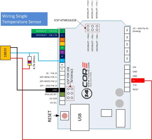
Electric Temperature Gauge Wiring Diagram Wiring Diagram 3 wire coolant temperature sensor wiring diagram. the two wires, a “5 volt reference”, and a “ground wire” go to the ecu, and the third wire “earth 1 wire for temp gauge” goes to the cluster mounted temperature gauge by providing an earth link to the temperature gauge. in three wire coolant temp sensors, the ecu does not control the. Wiring – connecting the ds18b20 to an arduino. connecting a ds18b20 to the arduino is fairly easy as you only need to connect 3 pins. start by connecting the gnd pin to ground and the v dd pin to the 5 v output of the arduino. next, connect the middle pin (dq) to any of the digital pins of the arduino.

Wiring The Ds18b20 1 Wire Temperature Sensor 14core The wiring diagram consists of several components which are connected to your car’s electrical system by wires. the sensor’s output signal is sent to a gauge or a warning light, where it is measured and monitored. the gauge or warning light is then activated if there is a problem with the cooling system. it is also useful to know the type. Here’s a summary of the most relevant specs of the ds18b20 temperature sensor: communicates over one wire bus communication. power supply range: 3.0v to 5.5v. operating temperature range: 55ºc to 125ºc. accuracy 0.5 ºc (between the range 10ºc to 85ºc) for more information consult the ds18b20 datasheet. A 3 wire pt100 wiring diagram is a diagram that illustrates how to properly connect a pt100 temperature sensor with three wires. pt100 is a type of resistance temperature detector (rtd) that is widely used in industrial applications to measure temperature accurately. it is designed to have a resistance of 100 ohms at 0 degrees celsius. The pt100 connection diagram is an essential tool for understanding the wiring configuration of a pt100 temperature sensor. pt100 sensors are commonly used in industrial applications to measure temperature, and the connection diagram helps ensure the correct installation and operation of these sensors.

Water Temperature Sensor Wiring Diagram A 3 wire pt100 wiring diagram is a diagram that illustrates how to properly connect a pt100 temperature sensor with three wires. pt100 is a type of resistance temperature detector (rtd) that is widely used in industrial applications to measure temperature accurately. it is designed to have a resistance of 100 ohms at 0 degrees celsius. The pt100 connection diagram is an essential tool for understanding the wiring configuration of a pt100 temperature sensor. pt100 sensors are commonly used in industrial applications to measure temperature, and the connection diagram helps ensure the correct installation and operation of these sensors. In this guide, we will explain the basics of pt100 4 wire wiring diagrams and provide you with a step by step guide on how to wire a pt100 sensor correctly. we will also discuss the advantages of using a 4 wire connection and the common mistakes to avoid when wiring a pt100 sensor. a 4 wire pt100 wiring diagram consists of four wires: two. The coolant temp sensor wiring diagram illustrates the electrical connections for the sensor. it typically includes the wire colors, connector pinouts, and any related components in the circuit. the diagram acts as a guide for mechanics, technicians, and car enthusiasts who need to understand how the sensor is wired to ensure accurate readings.

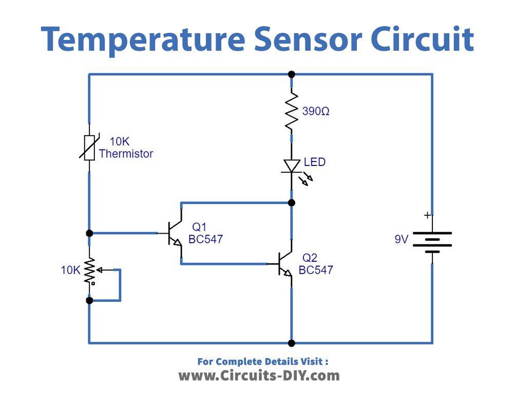
Temperature Sensor Circuit Using Thermistor In this guide, we will explain the basics of pt100 4 wire wiring diagrams and provide you with a step by step guide on how to wire a pt100 sensor correctly. we will also discuss the advantages of using a 4 wire connection and the common mistakes to avoid when wiring a pt100 sensor. a 4 wire pt100 wiring diagram consists of four wires: two. The coolant temp sensor wiring diagram illustrates the electrical connections for the sensor. it typically includes the wire colors, connector pinouts, and any related components in the circuit. the diagram acts as a guide for mechanics, technicians, and car enthusiasts who need to understand how the sensor is wired to ensure accurate readings.

Comments are closed.