Three Phase Electrical Wiring Diagram

Three Phase Electrical Wiring Installation In Home Nec Iec Tutorial Generally, electric supply and service providers install a single phase energy meter when load is less than 7.5kw (10hp) in domestic areas (consumer unit for home). if the limit is exceeded, then it’s recommended to install a 3 phase energy meter for consumer units. when load exceeds from 7.5 kw, then 3 phase electrical wiring is recommended. The wiring diagram for a 3 phase motor shows how the motor’s three windings are connected to the power supply and control circuits. each winding corresponds to one phase of the electrical system, and the proper phasing and sequencing of these windings is crucial for the motor’s operation. the wiring diagram typically includes information.

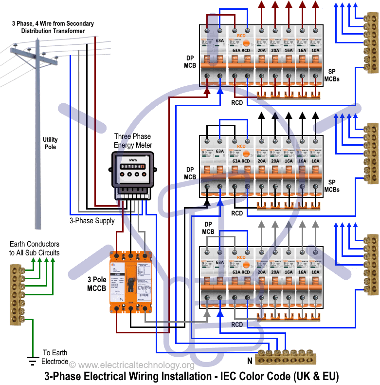
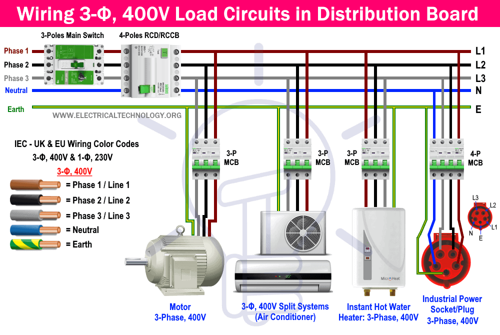
Three Phase Electrical Wiring Installation In Home Nec Iec When interpreting a three phase wiring diagram, it is important to understand the basic principles of three phase power. this includes knowledge of the phases (a, b, and c), the phase angles (120 degrees apart), and the concept of balanced and unbalanced loads. it is also essential to understand the different types of connections, such as star. Iec wiring color codes: 400v, 3 Φ: uk & eu. we have used the following iec wiring color codes for 400v three phase supply voltage applicable in the uk & eu. iec wiring color codes for 400v, 3 phase, 4 5 wire system. brown = phase 1 or line. black = phase 2 or line 2. gray = phase 3 or line 3. Fig 2: electrical wiring diagram of three phase & single phase consumer unit with rcd in multi storey bulding. good to know. in a three phase wiring distribution system (star connection i.e. 3 phase, 4 wire system); line to line voltage = 415v ac (208v in us) line to neutral voltage = 230v (120v in us) i.e. Industries or factories are installed with three phase power in order to connect heavy machineries and equipments. busbars carries this three phase power and from which individual connections are brought out ,to individual loads , through cables. the figure below shows schematic diagram for industrial three phase wiring.

Three Phase Electrical Wiring Installation In Home Nec Iec Fig 2: electrical wiring diagram of three phase & single phase consumer unit with rcd in multi storey bulding. good to know. in a three phase wiring distribution system (star connection i.e. 3 phase, 4 wire system); line to line voltage = 415v ac (208v in us) line to neutral voltage = 230v (120v in us) i.e. Industries or factories are installed with three phase power in order to connect heavy machineries and equipments. busbars carries this three phase power and from which individual connections are brought out ,to individual loads , through cables. the figure below shows schematic diagram for industrial three phase wiring. A 3 phase wiring diagram for homes shows the electrical connections between the utility power supply and the three phase panel in the home. the diagram illustrates the three phases (a, b, and c) with their respective hot wires and neutral wire. each phase carries a different voltage, typically 120 volts, resulting in a total of 208 volts. The 208v 3 phase wiring diagram illustrates the connections and components involved in a three phase electrical system. it shows how the three phases (labeled a, b, and c) are connected to the main electrical panel and distributed to different loads. it also includes information about the neutral wire and ground connections.

Comments are closed.