Two Digit Counter Circuit Using 7 Segment And Ic Ne 555 4026

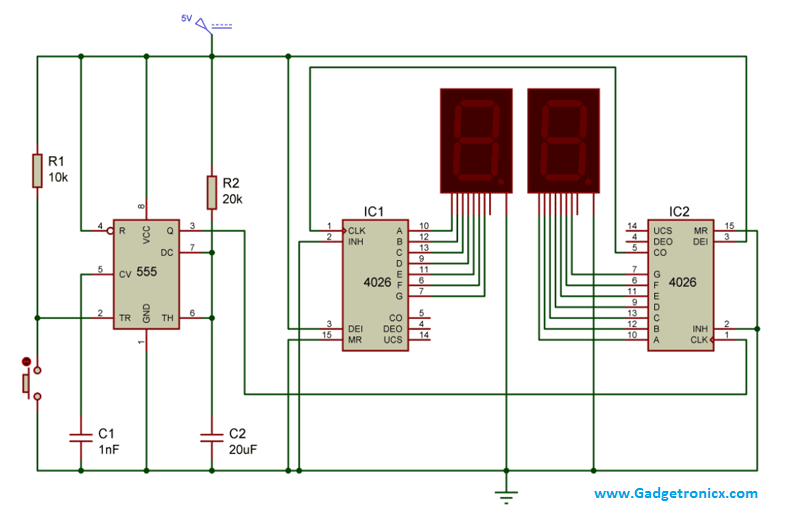
3 Digit Counter Circuit Diagram Here we are employing two 7 segments and two ic 4026 a seven segment display decade counter. and a ic 555 to feed the required pulse to the decade ic’s used in the above circuit. the whole circuit was designed to increment the count with a single push button switch. lets move into the working of this counter circuit. Ic cd4026. 4026 ic is a 4000 series ic. it is a cmos seven segment counter ic and can be operated at very low power. it is a decade counter, counts in decimal digits (0 9). it is used to display numbers on seven segment displays and it increment the number by one, when a clock pulse is applied to its pin 1.

7 Segment Counter Circuit Diagram This video is about the digital counter from (0 99) by 7 segment display, for that we used 555,cd4026 ic., 4026 is an ic which can perform the function of b. In this diy tutorial, we are demonstrating the project of a 7 segment counter using a ne555 timer and cd4026 ic. digital counters are required in this modern world, and seven segment displays are the best part to show the numbers. counters are required in the object or product counters, advanced stopwatches, calculators, clocks, and so forth. Working explanation. a simple circuit uses a 555 timer ic, a decade counter ic 4026 and a seven segment (common cathode type) led. the 555 ic is configured in a monostable multivibrator mode that produces a pulse each time the count key is pressed. the clock pulse is an input to the ic 4026 that counts each pulse and derives the seven segments led. The 7 segment display, also written as “seven segment display”, consists of seven leds (hence its name) arranged in a rectangular fashion as shown. each of t.

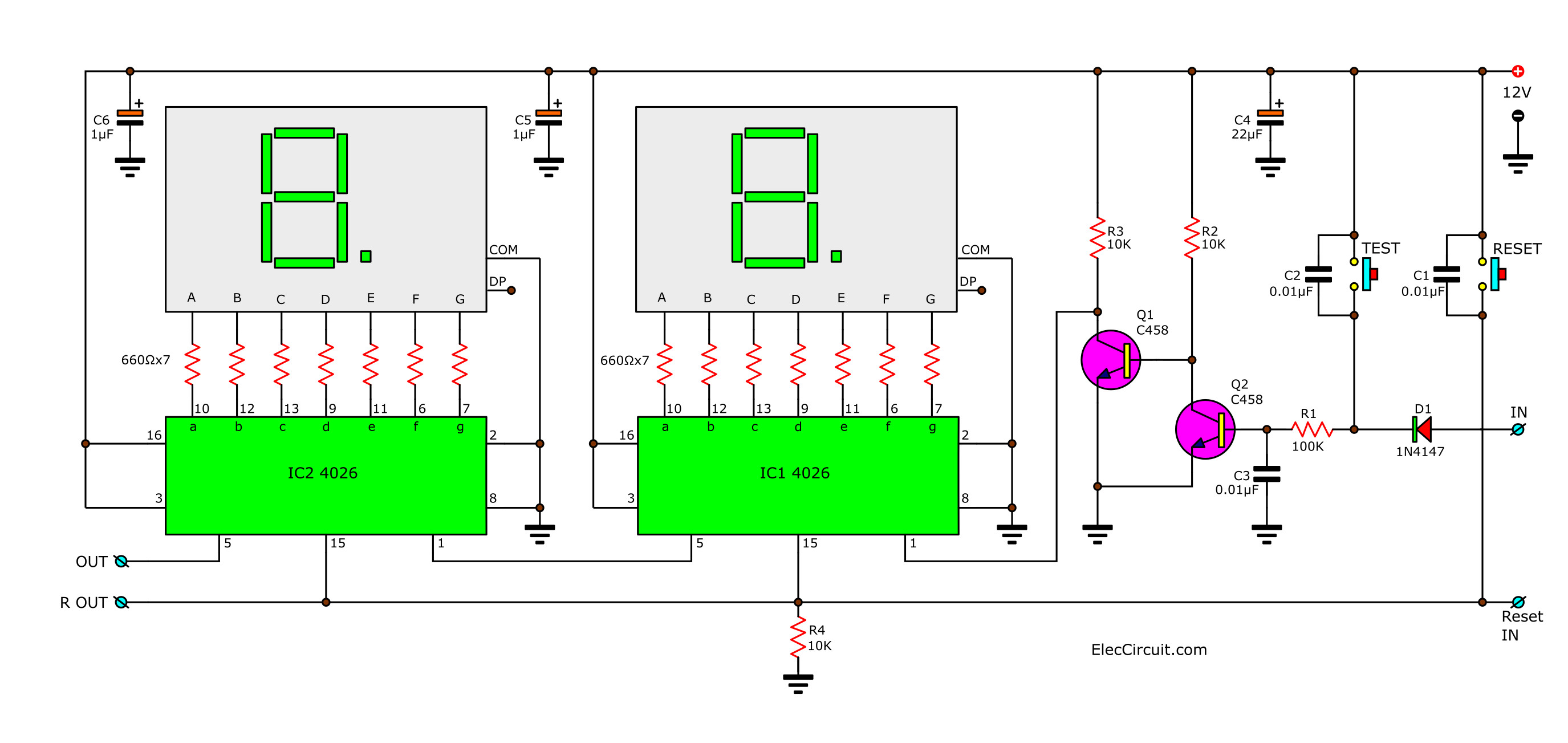
4 Digit Counter Circuit Diagram Working explanation. a simple circuit uses a 555 timer ic, a decade counter ic 4026 and a seven segment (common cathode type) led. the 555 ic is configured in a monostable multivibrator mode that produces a pulse each time the count key is pressed. the clock pulse is an input to the ic 4026 that counts each pulse and derives the seven segments led. The 7 segment display, also written as “seven segment display”, consists of seven leds (hence its name) arranged in a rectangular fashion as shown. each of t. To use a seven segment display with 555 timer ic, there is a 7 segment driver ic which is ic cd4026, so we are building 7 segment counter circuit using 4026. As the circuit below. the ic1, ic2 cd4026 (cmos counters decade divider integrated circuit). i like this ic. because they can drive led 7 segment directly. recommended: 0 99 counter using ttl 74ls48, 74ls90. which they connected together. ic1 is a unit counter ic. ic2 is a ten digit counter. and both ics will work at rising edged clock only.

2 Digit Simple Digital Counter Circuit Using Cd4026 To use a seven segment display with 555 timer ic, there is a 7 segment driver ic which is ic cd4026, so we are building 7 segment counter circuit using 4026. As the circuit below. the ic1, ic2 cd4026 (cmos counters decade divider integrated circuit). i like this ic. because they can drive led 7 segment directly. recommended: 0 99 counter using ttl 74ls48, 74ls90. which they connected together. ic1 is a unit counter ic. ic2 is a ten digit counter. and both ics will work at rising edged clock only.

Object Counter Circuit Diagram

Comments are closed.