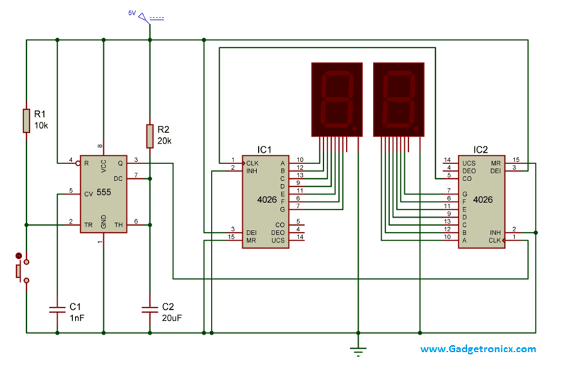
Two Digit Object Counter Circuit Using 7 Segment Display 555 Timer Ic

3 Digit Counter Circuit Diagram In this circuit we have used a comparator ( ic lm358) and ir transmitter and receiver pair for detecting a object. and then we have used a 555 timer ic to generate a pulse for triggering the seven segment decoder (cd4033) and two common cathode seven segment display units are connected with 7 segment decoder ic. 555 timer ic is configured in. View the full circuit tutorial here: circuitdigest electronic circuits object counter circuit diagramobject counters or product counters are impor.

Clock Circuit Using 555 Timer Ic It is a cmos seven segment counter ic and can be operated at very low power. it is a decade counter, counts in decimal digits (0 9). it is used to display numbers on seven segment displays and it increment the number by one, when a clock pulse is applied to its pin 1. means more the clock pulse rate, faster the numbers change in 7 segment display. 2 digit digital object counter. here is the circuit diagram of the door entry person counter project, this object counter circuit is used as a digital object counter using a two digit seven segment led display. this can also be called people or object counter circuit diagram using ic 555 and ic 4033 or digital ir counter to count door entries. The ic 555 timer functions as the trigger for the counter, while the cd4033 is responsible for counting and incrementing the counts. it then sends the output values to the 7 segment display, which shows the numbers in a readable format. in operation, a user provides a high frequency signal to the ic 555 timer, which triggers the cd4033 4 bit. Here we are employing two 7 segments and two ic 4026 a seven segment display decade counter. and a ic 555 to feed the required pulse to the decade ic’s used in the above circuit. the whole circuit was designed to increment the count with a single push button switch. lets move into the working of this counter circuit.

7 Segment Counter Circuit Diagram The ic 555 timer functions as the trigger for the counter, while the cd4033 is responsible for counting and incrementing the counts. it then sends the output values to the 7 segment display, which shows the numbers in a readable format. in operation, a user provides a high frequency signal to the ic 555 timer, which triggers the cd4033 4 bit. Here we are employing two 7 segments and two ic 4026 a seven segment display decade counter. and a ic 555 to feed the required pulse to the decade ic’s used in the above circuit. the whole circuit was designed to increment the count with a single push button switch. lets move into the working of this counter circuit. This video is about the digital counter from (0 99) by 7 segment display, for that we used 555,cd4026 ic., 4026 is an ic which can perform the function of b. In the wake of getting a pulse from 555 timer ic, we applied this to the timer pin of 7 segment decoder (u4) and afterward completed the signal (pin 5) to the timer pin of another 7segment decoder (u3). in the wake of getting pulse from 555 timer ic, 7 segment counter changes number values of 7 segment display.

Comments are closed.