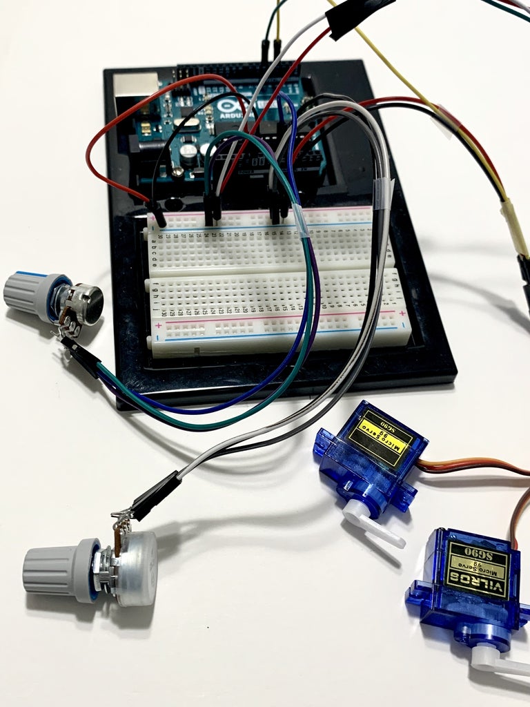
Two Servo Control With Potentiometer And Arduino

2 Potentiometers 2 Servos Controlled Motion With Arduino 4 Steps Plug the servo into to the breadboard and arduino: servo 1: use a color jumper wire to connect it's input signal port to the digital pwm port, 5 on the arduino. plug the red jumper wire into v5 terminal strip and a black jumper wire into gnd terminal strip in series with potentiometer layout (refer to image). servo 2: use a color jumper wire to. Connect arduino to pc via usb cable. open arduino ide, select the right board and port. copy the above code and open with arduino ide. click upload button on arduino ide to upload code to arduino. open serial monitor. rotate the potentiometer. see the servo motor's rotation. see the result on serial monitor. com6.

How To Control 2 Servo Or More With Potentiometers Using Arduino Controlling 2 servos using 2 potentiometers (variable resistor) by daniel wright 2010 01 14 based on the tutorial sketch #include <servo.h> servo myservo1; create servo object to control the first servo servo myservo2; create servo object to control the second servo int potpin1 = 0; analog pin used to connect the first potentiometer int val1; variable to read the value. Red input power input (vcc) brown input ground input (gnd) the potentiometer connections we use in this project are as follows; two outer pins are power (vcc) and ground (gnd) middle pin is signal pin. the servo1 vcc and gnd connect to the breadboard's vcc gnd inputs. the servo1 signal connect to the arduino digital pwm 3. Control the servo with a potentiometer. let’s attach a rotary 10kΩ potentiometer, and adjust our sketch to enable us control of the motor by turning the knob. here’s the new circuit: connect the middle of the potentiometer pin to analog pin 0 (a0) on the arduino. the other two pins connect to 5v and gnd. Arduino code explanation. the complete arduino code for multiple servo control is given at the end. arduino has library for servo motors and it handles all the pwm related things to rotate the servo, you just need to enter the angle to which you want to rotate and there is function servo1.write (angle); which will rotate the servo to desired.

2 Potentiometers 2 Servos Controlled Motion With Arduino 4 Steps Control the servo with a potentiometer. let’s attach a rotary 10kΩ potentiometer, and adjust our sketch to enable us control of the motor by turning the knob. here’s the new circuit: connect the middle of the potentiometer pin to analog pin 0 (a0) on the arduino. the other two pins connect to 5v and gnd. Arduino code explanation. the complete arduino code for multiple servo control is given at the end. arduino has library for servo motors and it handles all the pwm related things to rotate the servo, you just need to enter the angle to which you want to rotate and there is function servo1.write (angle); which will rotate the servo to desired. Example code 2: controlling the servo with the potentiometer. this example sketch uses the potentiometer to control the position of the servo motor. when you turn the potentiometer, the servo motor should move correspondingly to the position dictated by the potentiometer’s resistance. this code is based on the basic arduino potentiometer example. Step by step wiring is explained, code explained and demonstrated. variable resistor is some people call potentiometer. the best thank you for me is to not t.

Control 2 Or More Servo With Potentiometers Using Arduino Robojax Example code 2: controlling the servo with the potentiometer. this example sketch uses the potentiometer to control the position of the servo motor. when you turn the potentiometer, the servo motor should move correspondingly to the position dictated by the potentiometer’s resistance. this code is based on the basic arduino potentiometer example. Step by step wiring is explained, code explained and demonstrated. variable resistor is some people call potentiometer. the best thank you for me is to not t.

Comments are closed.