Two Wire Alternator Wiring Diagram

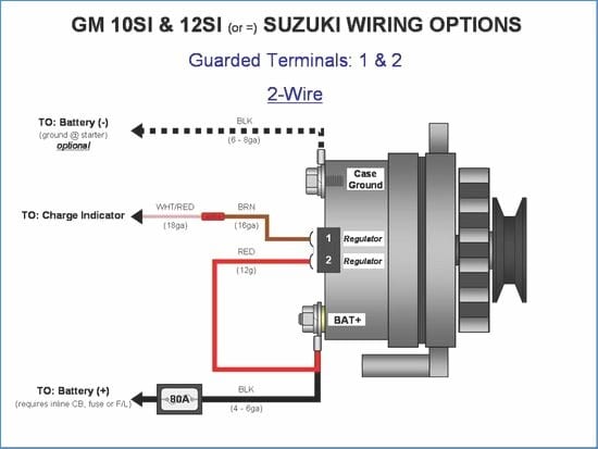
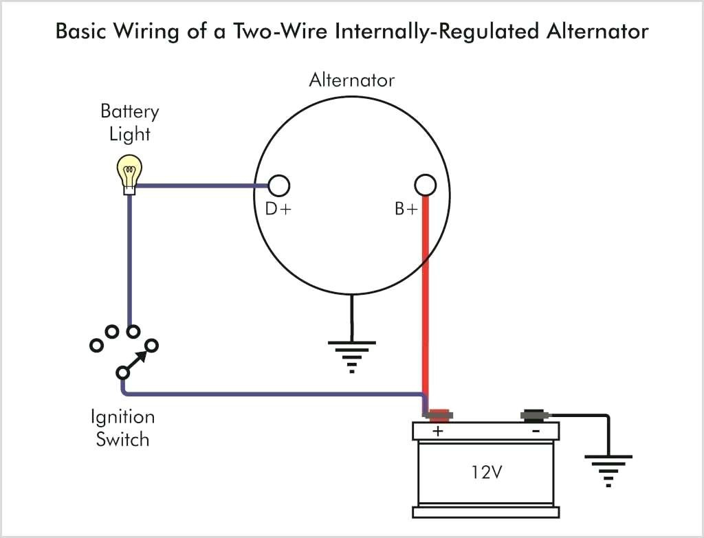
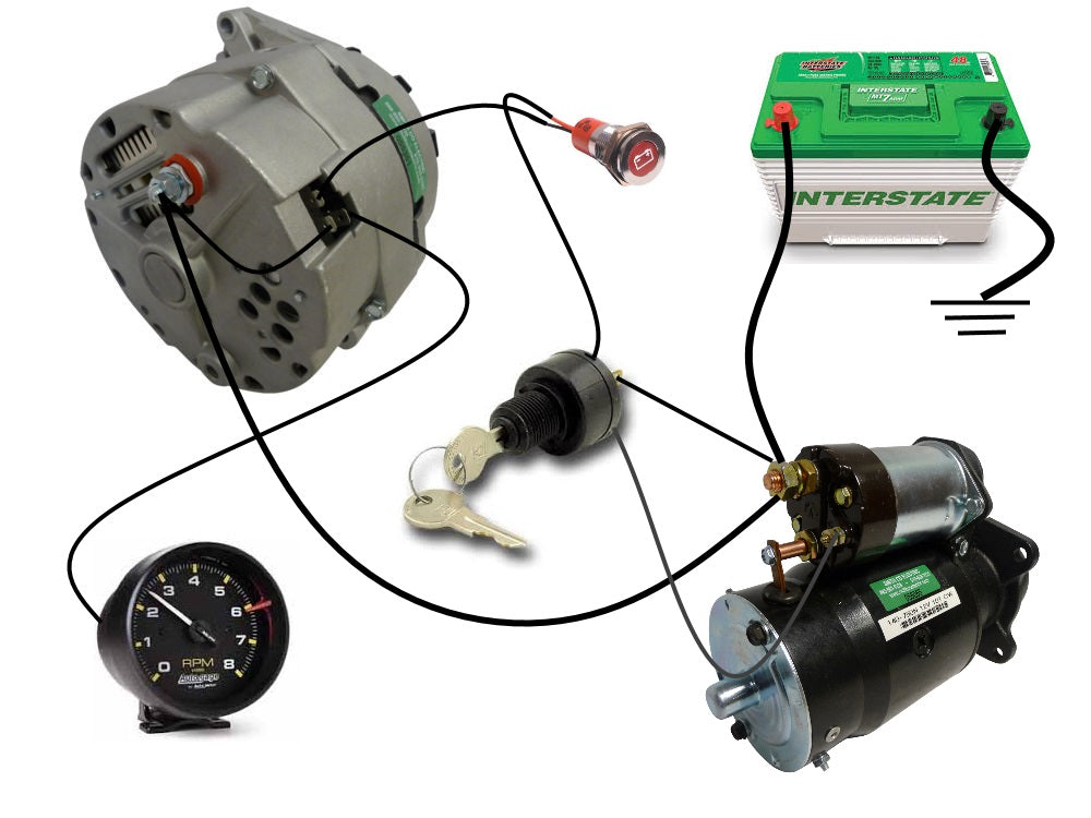
Wiring A 2 Wire Alternator Learn how the 2 wire alternator works and how to wire it properly. see the diagram and step by step instructions for connecting the b and l terminals to the battery and dashboard. Learn how a 2 wire alternator system works and how to wire it correctly. find out the benefits, components, and functions of a 2 wire alternator and see a sample diagram.

Delco 2 Wire Alternator Wiring Diagram Learn how to wire the exciter wire on different types of alternators: one wire, two wire, and three wire. the exciter wire connects the voltage regulator to the alternator and is essential for starting your car. Learn how to wire a delco remy 2 wire alternator with a simple and clear diagram. find out the basic functioning, benefits, and compatibility of this type of alternator for your vehicle. Auto alternator wiring diagram: what wires go where? if you consider a standard gm alternator with an inbuilt regulator, most people refer to it as a three wire alternator. however, in a real sense, only 2 wires are going in and out: the positive battery wire and the exciter wire. the positive battery wire is larger in diameter and red in color. The alternator wiring diagram for the b , d , and w terminals provides insight into the connection and operation of these terminals. 1. b terminal: the b terminal, also known as the battery positive terminal, is responsible for providing power to the alternator. it is connected directly to the positive terminal of the vehicle’s battery.

Two Wire Alternator Diagram Auto alternator wiring diagram: what wires go where? if you consider a standard gm alternator with an inbuilt regulator, most people refer to it as a three wire alternator. however, in a real sense, only 2 wires are going in and out: the positive battery wire and the exciter wire. the positive battery wire is larger in diameter and red in color. The alternator wiring diagram for the b , d , and w terminals provides insight into the connection and operation of these terminals. 1. b terminal: the b terminal, also known as the battery positive terminal, is responsible for providing power to the alternator. it is connected directly to the positive terminal of the vehicle’s battery. A typical 3 wire alternator wiring diagram with an internal voltage regulator. computer controlled voltage regulation many late model vehicles use the engine computer, which is often referred to as the powertrain control module (pcm), to control alternator output. Learn about the two wires on an alternator and how they connect to the battery, voltage regulator, and engine. see the differences between three wire, electromechanical, and pcm controlled alternators and how they work.

Comments are closed.