Vw Fan Control Module Wiring Diagram Wiring Diagram And Schematics

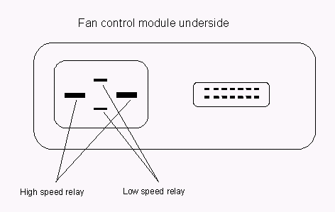
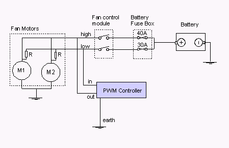
Diagram Assembly Diagram Of Engine Cooling Fan Module Mydiagram Online For those looking for this info later, i mapped out the connections from the vw wiring diagram. for me my fcm was part number 1j0919506h. this confirms the differences i was seeing with my 10 pin fcm, in particular the primary 12v power going to pin t4 4 (whereas 14 pin fcm have 12v power at t4 1). hope this helps someone else. While the fan control module (j293) is dumb as dirt, it does monitor amp draw of the a c clutch (n25). if the draw is out of factory design (open or short circuit), the fan control module (j293) can cut power to the a c clutch (n25). a c clutch (n25) should be about 4.5 ohms. boostedgli, hmc, boki ar and 5 others. do not ask questions here!.

Mk4 Golf Wiring Diagram Wiring Diagram 23065 posts · joined 2003. #2 · dec 7, 2008. re: radiator fan wiring diagram (tmroper1331) red white = comes from the coolant fan control module. red black = comes from the coolant fan control module (wire connection, in coolant fan wiring harness) brown = ground (always!) red = 12v [confirm with test light or multimeter]. Sb38 is a 10a fuse that is probably power supply for the fan control module, feeds the 1mm blue wire with red stripe (bl ro). upper left corner in engine bay fuse box, 3rd from left. this fuse powers: camshaft adjustment valve 1 n205 , coolant fan control (fc) control module j293 . Variable duty cycle signal from the instrument cluster j285 when the engine is not overheating, 0% duty cycle when the engine is overheating. use the vas 5051 dso to read this signal: 5 v div, 100 ms div. note: when overheating, this signal will switch the a c compressor off and switch the radiator fan to 2nd speed. t14 14. Here is a pdf of the wiring diagrams and component locations for the mk6 golf gti. it has proper section bookmarks and can be searched with a pdf viewer find tool. some of the diagrams are a little squished from being fit to page. there are also a lot of icons links throughout the pages that.

Schema Koelfan V6 Vwforum Nl Variable duty cycle signal from the instrument cluster j285 when the engine is not overheating, 0% duty cycle when the engine is overheating. use the vas 5051 dso to read this signal: 5 v div, 100 ms div. note: when overheating, this signal will switch the a c compressor off and switch the radiator fan to 2nd speed. t14 14. Here is a pdf of the wiring diagrams and component locations for the mk6 golf gti. it has proper section bookmarks and can be searched with a pdf viewer find tool. some of the diagrams are a little squished from being fit to page. there are also a lot of icons links throughout the pages that. You can find detailed instructions on how to access the wiring diagram, myplatinumcard and other websites offering multiple wiring diagrams to assist car owners with their 2000 vw beetle fan control module. when troubleshooting the fan control module, having access to an accurate wiring diagram is essential. with the aid of an accurate. 13 component symbol with open drawing side indicated component is continued on another wiring diagram. 14 internal connections (thin lines) these connections are not wires. internal connections are current carrying and are listed to allow tracing of current flow inside components and wiring harness.

Comments are closed.