Water Temp Electric Temperature Gauge Wiring Diagram

Electric Temperature Gauge Wiring Diagram Wiring Diagram A Step 2: identify the appropriate wires. refer to the wiring diagram provided with the electric water temp gauge to identify the appropriate wires for the power, ground, and sender. it is important to match the colors and labels correctly to ensure proper functionality. step 3: connect the power wire. Asalam o alyikum,friends, in this video we will learn about the water temperature gauge complete wiring practically, that how can we installed the water temp.

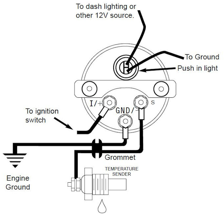
Vdo Temp Sensor Gauge Ybw Forum Use #2260 weld on bung on steel pans (not included).cylinder head temp. head must be drilled and tapped for 1⁄8" npt hole. s. nder should be grounded automatically when instal. ed. if not, proper ground connections sho. d be made. be sure not to drill all the way through.diff. temp: install temperature s. 5. detected, determine the cause of the leak and repair. connect the white wire to dash lighting or switchable 12v light source, the red wire to switched 12v source and the black wire to ground.(see diagram for details) 6. install temperature sender. water temp: install temperature sender. 1 8" npt. for 3 8" npt or 1 ". The autometer electric water temp gauge comes with a wiring diagram, which provides instructions on how to properly connect and install the gauge in the vehicle. it typically includes information on the necessary electrical connections, such as power, ground, and temperature sensor wires. Connect one end to terminal post on temperature sender, and opposite end to sender (s) terminal on back of gauge. 3. route 18 gage wire from center terminal gnd ( ) on back of gauge to good ground near sender. 4. connect wire from ignition switch to ignition (i) terminal on back of gauge. 5. reconnect negative ( ) battery cable.

Electric Temperature Gauge Wiring Diagram Wiring Diagram The autometer electric water temp gauge comes with a wiring diagram, which provides instructions on how to properly connect and install the gauge in the vehicle. it typically includes information on the necessary electrical connections, such as power, ground, and temperature sensor wires. Connect one end to terminal post on temperature sender, and opposite end to sender (s) terminal on back of gauge. 3. route 18 gage wire from center terminal gnd ( ) on back of gauge to good ground near sender. 4. connect wire from ignition switch to ignition (i) terminal on back of gauge. 5. reconnect negative ( ) battery cable. Auto meter competition instruments demonstrates how to install a basic water temperature gauge and what components are needed to complete the install. insta. Use wire connectors and crimpers to secure the connections. 5. connect the gauge backlight: if your water temperature gauge has a backlight, connect one end of an electrical wire to the positive terminal of the gauge and the other end to a suitable power source. use a fuse holder and a fuse to protect the circuit.

Comments are closed.