Welding Blueprint Symbols Signs Explained W Chart

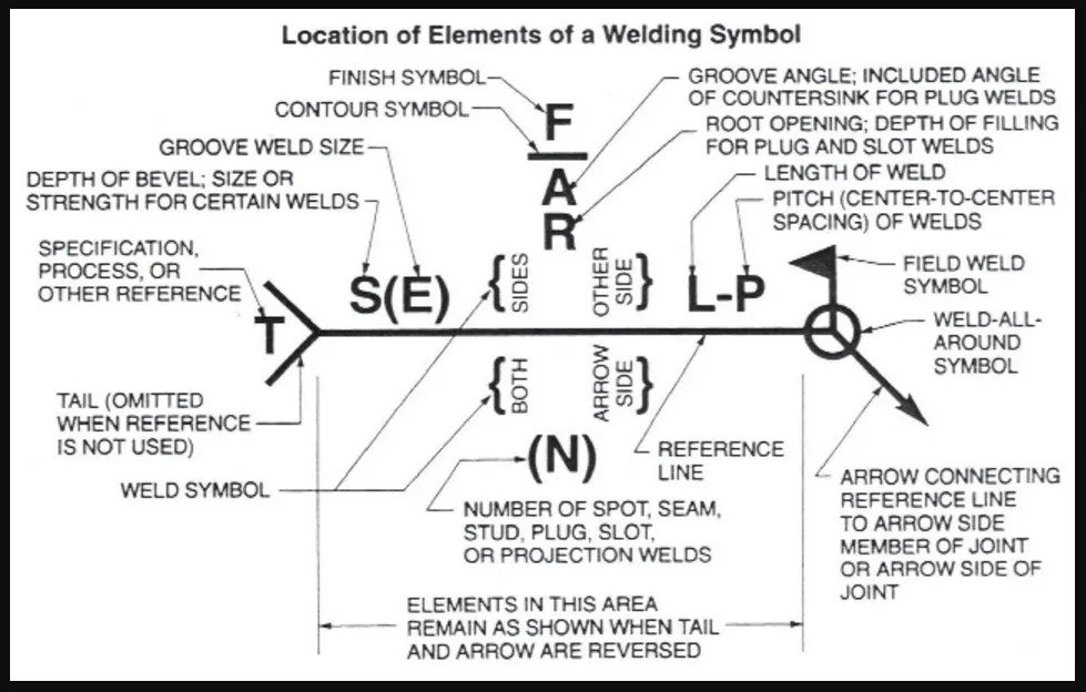
Welding Blueprint Symbols Signs Explained W Chart Welding symbols, also referred to as weld callouts and welding drawing symbols, contain information pertinent to the weld as previously mentioned. below is a comprehensive list of what one can expect to see on a welding symbol, as well as an example image and list of options for each aspect of the welding symbol. the arrow 1. Spacer – this symbol indicates the type and the dimension of the spacer that is inserted between the welded pieces. weld all around – it signals that the weld is to be made over the entire circumference. flag symbol – field weld made on site. contour – these symbols designate the final weld end product contour.

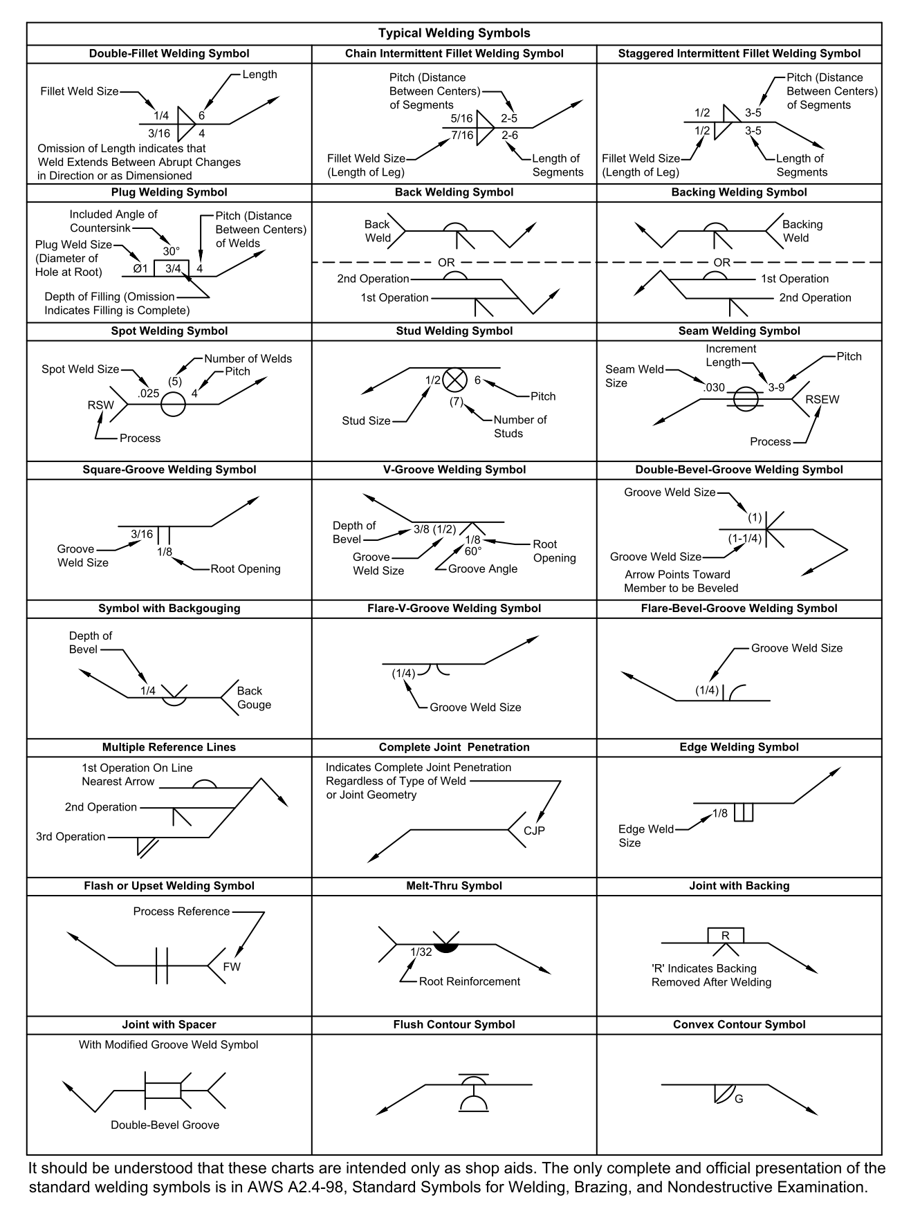
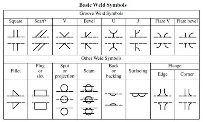
Welding Symbols Chart Printable Customize And Print Following are all the other base welding symbols that are not butt welds, including the fillet symbol. fillet. this symbol has a right angled triangle, since the most common fillet joint is between two plates at a right angle to each other. usually, it’s between a 90° joint, or somewhere close. plug. Weld symbols are a key part of welding documentation, and understanding how to read weld symbols is critical for welders. there are three main elements to a weld symbol: tail. the reference line is a horizontal line that is used to align the other elements of the symbol. the arrow is used to point to the location of the weld, and the tail. To learn more about the structure of welding symbols, download the aws a2.4:2007 standard symbols for welding, brazing, and nondestructive examination. how to read 6 welding blueprint symbols. welding blueprint reading starts with understanding the different types of welds and their symbols. The tail of the weld symbol is the place for supplementary information on the weld. it may reference the welding process, electrode or any helpful information that doesn't have a place on the symbol. types of welds and their symbols. each welding position has its own basic symbol. this is typically placed near the center of the reference line.

Welding Blueprint Symbols Signs Explained W Chart To learn more about the structure of welding symbols, download the aws a2.4:2007 standard symbols for welding, brazing, and nondestructive examination. how to read 6 welding blueprint symbols. welding blueprint reading starts with understanding the different types of welds and their symbols. The tail of the weld symbol is the place for supplementary information on the weld. it may reference the welding process, electrode or any helpful information that doesn't have a place on the symbol. types of welds and their symbols. each welding position has its own basic symbol. this is typically placed near the center of the reference line. 5. for instance. (example 1) indication: weld height is 3, staggered welding, weld seam length is 50, interval is 30, site welding is required. example 2: statement: spot weld diameter is 5, the number of spot welds is 10, and the interval is 30. example 3: indication: the weld height is 3, with full welding around. Reading welding blueprints. the first step in correctly interpreting a welding symbol is to identify the basic elements of the symbol. the arrow always points toward the weld location. the reference line is connected to the arrow line and weld symbols are placed on it. the weld size is always placed on the left side of the symbol.

Understanding The Basic Welding Symbols 5. for instance. (example 1) indication: weld height is 3, staggered welding, weld seam length is 50, interval is 30, site welding is required. example 2: statement: spot weld diameter is 5, the number of spot welds is 10, and the interval is 30. example 3: indication: the weld height is 3, with full welding around. Reading welding blueprints. the first step in correctly interpreting a welding symbol is to identify the basic elements of the symbol. the arrow always points toward the weld location. the reference line is connected to the arrow line and weld symbols are placed on it. the weld size is always placed on the left side of the symbol.

Comments are closed.