What Is A Contactor How To Use A Contactor How To Wiring A Power Contactor

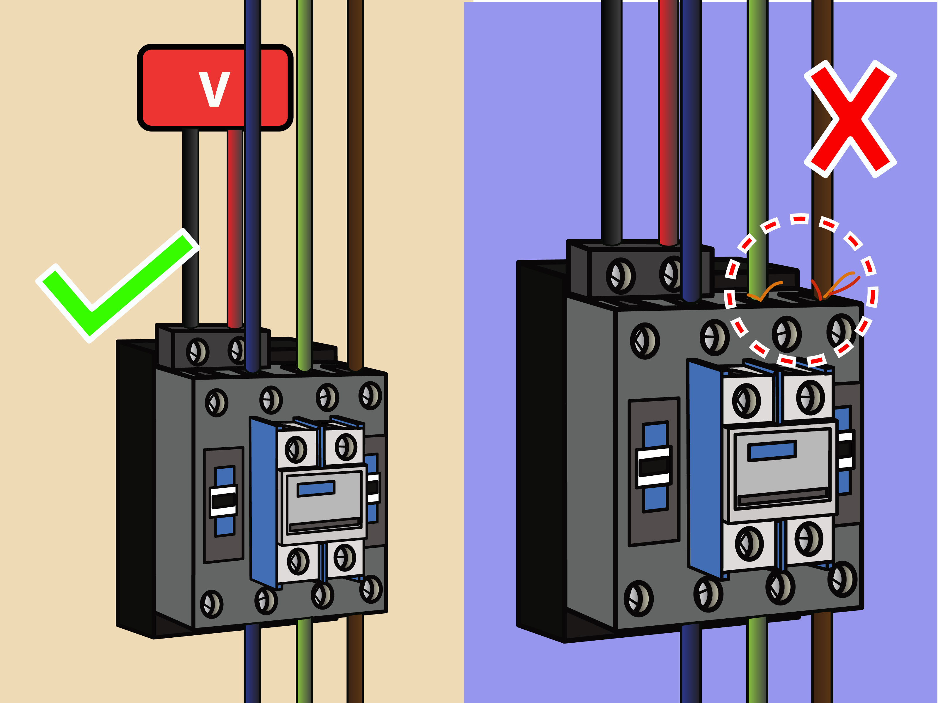
220 Volt Contactor Wiring Diagram Route the wires. remove all power to the wires. run all input and output wires to the contactor. these wires should be rated in the manufacturer information. use wire strippers to cut excess length off of the ends of the wire, making sure that the wires are long enough to reach the intended contact. The contactor wiring diagram typically includes information about the type and size of contactors used, as well as the control circuitry. it shows how the incoming power supply is connected to the contactors, and how the contactors are connected to the load or equipment being controlled.

How To Wire A Contactor 8 Steps With Pictures Wikihow 240 Volt An electrical contactor is used in a wide range of situations where there is a need to switch power to a circuit repeatedly. like relay switches, they are designed and built to perform this task over many thousands of cycles. contactors are mainly chosen for higher power applications than relays. The 3 phase motor contactor is an essential component in motor control systems as it provides a safe and reliable method of controlling the power supply. it helps to protect the motor from overload, short circuits, and other electrical faults. it also allows for remote control and automation of motor operations. What is a contactor? | working principles. How to wire a contactor single phase.first let's start with the common question what is a contactor?a contactor is an electrically controlled switch used for.

Single Phase Contactor Wiring Diagram A1 A2 What is a contactor? | working principles. How to wire a contactor single phase.first let's start with the common question what is a contactor?a contactor is an electrically controlled switch used for. The importance of a1 and a2 terminals in a contactor wiring diagram. in a contactor wiring diagram, the a1 and a2 terminals play a crucial role in the functioning of the contactor. these terminals are used for power supply connections and control circuit connections respectively. the a1 terminal is typically connected to the neutral wire or one. To wire a single phase magnetic contactor, follow the steps below: disconnect the power supply to the circuit to ensure safety. connect the incoming power line to the power terminals of the contactor. connect one end of the control switch or push button to the control terminal of the contactor.

How To Wire A Contactor Tipsmake The importance of a1 and a2 terminals in a contactor wiring diagram. in a contactor wiring diagram, the a1 and a2 terminals play a crucial role in the functioning of the contactor. these terminals are used for power supply connections and control circuit connections respectively. the a1 terminal is typically connected to the neutral wire or one. To wire a single phase magnetic contactor, follow the steps below: disconnect the power supply to the circuit to ensure safety. connect the incoming power line to the power terminals of the contactor. connect one end of the control switch or push button to the control terminal of the contactor.

How To Connect A Contactor Single Phase

Comments are closed.