What Is A Lamp In Circuit в Wiring Diagram

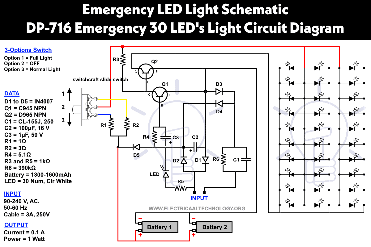
Wiring Diagram For Lighting Circuit Wiring Flow Schema These diagrams provide step by step instructions on how to connect the different components of a lamp, such as the socket, switch, and cord, in the correct way. by following these diagrams, it becomes much easier to assemble and wire a lamp correctly, ensuring that it functions properly and safely. one common type of lamp wiring diagram is the. When the connections are made properly, the circuit will “close” (controlled by a switch) and current will flow through the circuit and light the lamp. the current is a flow of electrical charge within the circuit that powers the lamp. the current flows into the lamp cord via the 'hot' wire and returns to the source via the 'neutral' wire.

Simple Lamp Wiring Diagram Here a 2 way push button switch is wired to a lamp with 2 bulbs. this diagram can be used to rewire an old push button lamp with a new switch replacement. the hot wire from the cord is connected directly to the black wire on the switch and the neutral is spliced to the neutral contact on each bulb sockets. the red and blue wires from the switch. Domestic lighting wiring diagrams are essential tools for electricians and homeowners who are dealing with the installation or repair of lighting systems in their homes. these diagrams provide a visual representation of how the electrical wiring is connected and the components involved in the lighting system. when analyzing a domestic lighting. Here’s a step by step guide to the wiring process: step 1: begin by running a cable from the power source (distribution board) to the light fixture. important: do not connect this cable to the power source until the entire circuit is completed and tested in accordance with bs 7671 regulations, including a safe isolation procedure. step 2. Radial (or junction box) wiring. picture 2 below shows a typical radial (or junction box) lighting system, a two core and earth cable runs from the consumer unit to a series of junction boxes one for each lighting point (ceiling rose). from each junction box a separate cable runs to the light and another runs to the switch.

Diagram Lava Lamp Circuit Diagram Mydiagram Online Here’s a step by step guide to the wiring process: step 1: begin by running a cable from the power source (distribution board) to the light fixture. important: do not connect this cable to the power source until the entire circuit is completed and tested in accordance with bs 7671 regulations, including a safe isolation procedure. step 2. Radial (or junction box) wiring. picture 2 below shows a typical radial (or junction box) lighting system, a two core and earth cable runs from the consumer unit to a series of junction boxes one for each lighting point (ceiling rose). from each junction box a separate cable runs to the light and another runs to the switch. Step by step wiring instructions. 1. identify the wires: locate the electrical wires in the ceiling junction box. there should be three wires: black (hot), white (neutral), and green or bare copper (ground). 2. prepare the wires: using wire strippers, remove about 1 2 inch of insulation from the ends of each wire. 3. The most common resistor symbols include a zigzag line and a rectangle with a diagonal line. these symbols indicate the presence of resistance in a circuit, which limits the flow of electrical current. 5. lamp and light symbols. lamp and light symbols are used to represent lighting elements in wiring diagrams.

How To Wire A 3 Way Lamp Socket Step by step wiring instructions. 1. identify the wires: locate the electrical wires in the ceiling junction box. there should be three wires: black (hot), white (neutral), and green or bare copper (ground). 2. prepare the wires: using wire strippers, remove about 1 2 inch of insulation from the ends of each wire. 3. The most common resistor symbols include a zigzag line and a rectangle with a diagonal line. these symbols indicate the presence of resistance in a circuit, which limits the flow of electrical current. 5. lamp and light symbols. lamp and light symbols are used to represent lighting elements in wiring diagrams.

Comments are closed.