What Is Drum Brake Parts Working And Diagram

Drum Brake Diagram Working Explained Working of drum brake. when the driver presses the brake pedal, the brake booster (vacuum servo) increases the force, which the master cylinder converts to hydraulic pressure (oil pressure). the pressure is transferred to the brakes on the wheels ( brake fluid) by means of a tube filled with brake oil. the applied pressure pushes the pistons on. A drum brake is a brake that uses friction caused by a set of shoes or pads that press outward against a rotating cylinder shaped part called a brake drum. a brake drum is a cylindrical drum that is attached to the inside of a car’s wheel, and so rotates at the same speed as the wheel. the drum surrounds a set of brake shoes that are coated.

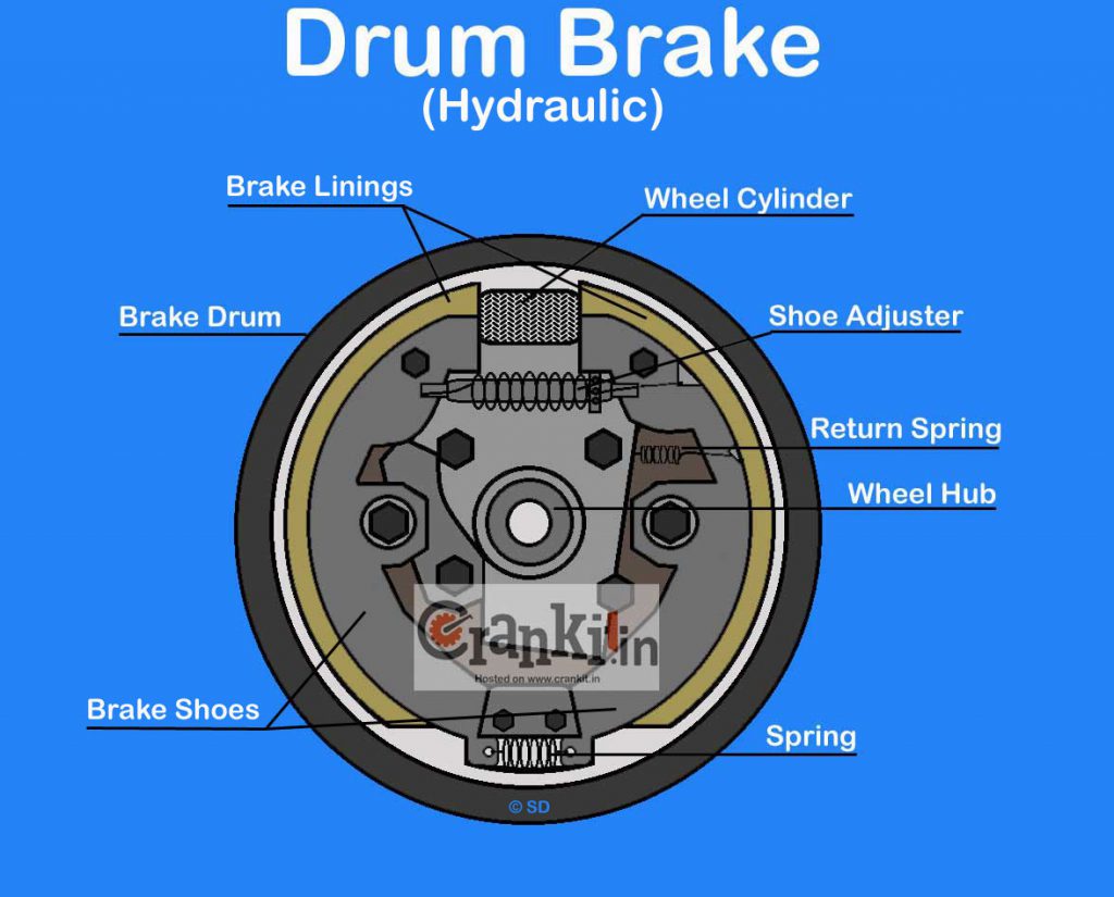
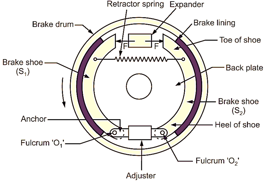
Drum Brake Diagram Working Explained The extra braking force provided by the wedging action allows drum brakes to use a smaller piston than disc brakes. but, because of the wedging action, the shoes must be pulled away from the drum when the brakes are released. this is the reason for some of the springs. other springs help hold the brake shoes in place and return the adjuster arm. Drum brake diagram. . now let's put it all together. the drum brake diagram below shows how all the parts of the brake work together. for more brake topics and links to related auto articles, check out the links below. . 1 … 5 6. please copy paste the following text to properly cite this howstuffworks article:. Drum brake construction. a drum brake comprises the following components: 1. backing plate: provides a solid base for other components in the drum brake attached to the axle sleeve. 2. brake drum: bolted to the wheel hub and spins with the wheel. often made of cast iron, and is resistant to heat and wear. The drum brake assembly diagram consists of several key components, each playing a crucial role in the functioning of the brake system. these include the brake drum, brake shoe, wheel cylinder, brake adjuster, return springs, and hold down springs. the brake drum is a large, hollow cylinder that fits over the brake shoes.

What Is Drum Brake Working Diagram Construction Applications Drum brake construction. a drum brake comprises the following components: 1. backing plate: provides a solid base for other components in the drum brake attached to the axle sleeve. 2. brake drum: bolted to the wheel hub and spins with the wheel. often made of cast iron, and is resistant to heat and wear. The drum brake assembly diagram consists of several key components, each playing a crucial role in the functioning of the brake system. these include the brake drum, brake shoe, wheel cylinder, brake adjuster, return springs, and hold down springs. the brake drum is a large, hollow cylinder that fits over the brake shoes. Discover the different parts of a drum brake system with the help of a detailed diagram. understand how each component works together to create friction and slow down the rotation of the drum brake. learn about the drum, shoes, wheel cylinder, springs, and other important components in this informative article. The parts diagram of drum brakes provides a visual representation of the components that make up this braking system. understanding these parts is essential for grasping the functionality of drum brakes and how they work. one of the main components displayed in the parts diagram is the brake drum. this round, hollow component is attached to the.

Comments are closed.