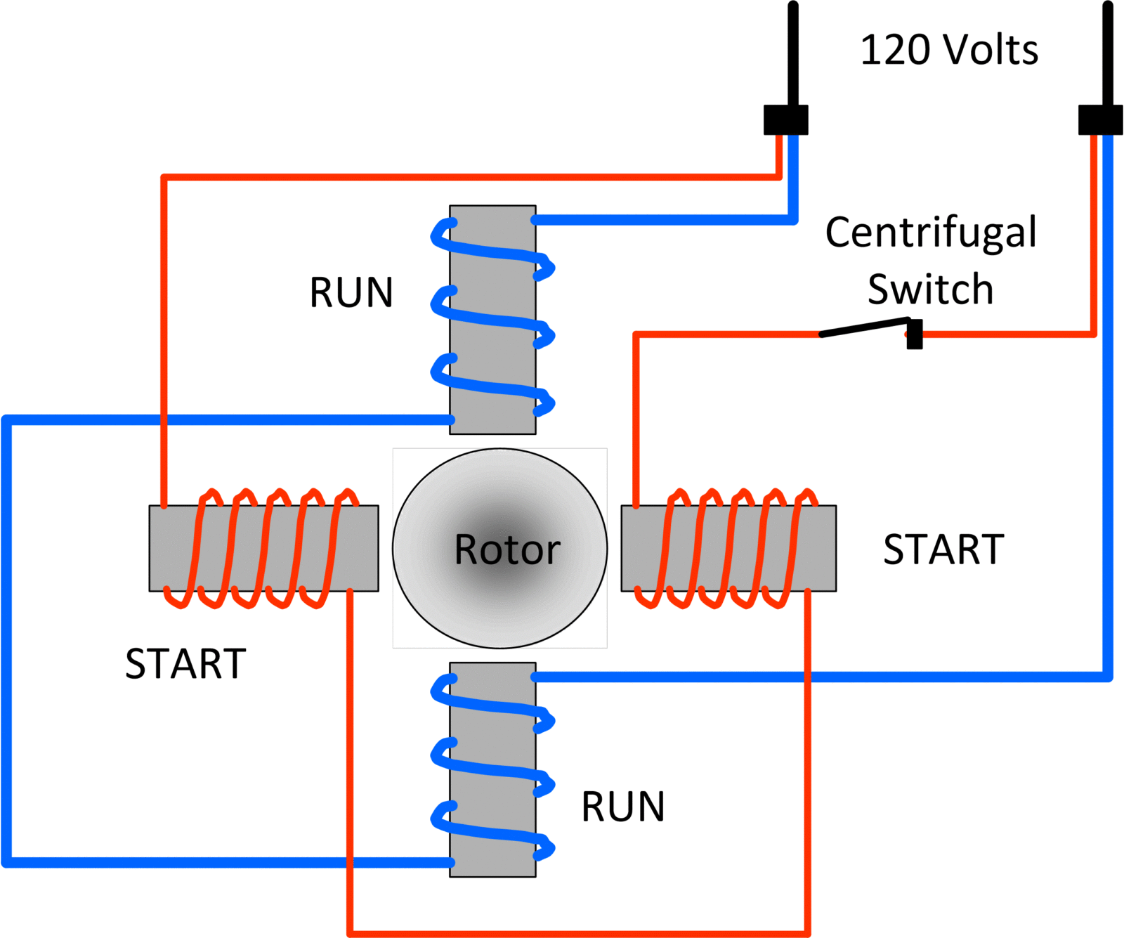
Wiring A Dc Motor Schematic And Wiring Diagram

How To Connect Wires To Dc Motor Using any method of connecting the wires, securely attach the potentiometer to the power supply using one wire, attached on both ends, or by connecting the components directly together. 5. connect the potentiometer to one terminal of the dc motor. attach the wire to the unused middle pin on the potentiometer. 2. identify the motor terminals: dc motors typically have two terminals labeled “positive” and “negative” or “red” and “black”. these terminals are where the power will be connected. 3. connect the power source: take one wire from the power source and connect it to the positive terminal of the dc motor.

Ac Dc Motor Wiring In this section, we will discuss how to wire a 4 wire dc motor for speed control, providing you with a step by step guide to ensure a successful setup. step 1: identify the motor terminals. the first step in wiring a 4 wire dc motor for speed control is to identify the motor terminals. typically, a 4 wire dc motor has 2 pairs of wires. A dc motor wiring diagram will quickly show you the connections between these components. it typically consists of a simple diagram that outlines the positive and negative power sources, the switch, and the motor load connections. it's important to properly install the wires within the motor terminal blocks and ensure that the polarity between. Motor wiring diagram d.c. motor connections your motor will be internally connected according to one of the diagrams shown below. these connections are in accordance with nema mg 1 and american standards publication 06. 1 1956. use figure 1 if your motor has a single voltage shunt field. use figure 2 if your motor has a dual voltage shunt field. Step 1: identify the motor’s wires. before beginning the wiring process, take a moment to identify the different wires coming from the motor. typically, you will find three main wires: the power wire, the neutral wire, and the ground wire. the power wire is usually black, the neutral wire is white, and the ground wire is usually green or bare.
Dc Motor Wiring Diagram 2 Wire Motor wiring diagram d.c. motor connections your motor will be internally connected according to one of the diagrams shown below. these connections are in accordance with nema mg 1 and american standards publication 06. 1 1956. use figure 1 if your motor has a single voltage shunt field. use figure 2 if your motor has a dual voltage shunt field. Step 1: identify the motor’s wires. before beginning the wiring process, take a moment to identify the different wires coming from the motor. typically, you will find three main wires: the power wire, the neutral wire, and the ground wire. the power wire is usually black, the neutral wire is white, and the ground wire is usually green or bare. Step 1: gather the necessary materials. before you begin wiring the dc motor, gather all the necessary materials. this includes the motor itself, a power supply, a switch, wire strippers, electrical tape, and the appropriate wires. make sure the wires are of the correct gauge for the power requirements of the motor. A 2 wire dc motor is typically used in applications where only basic functionality is required, such as in simple fans or small appliances. the wiring diagram for a 2 wire dc motor consists of two terminals: positive ( ) and negative ( ). these terminals are usually marked on the motor housing or in the manufacturer’s documentation.

Comments are closed.