Wiring A Dol Starter

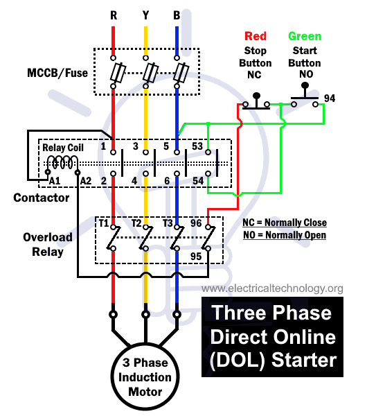
Dol Starter Connection And Wiring Diagram With Olr Etechnog Dol starter (direct on line starter) diagram and working. Working of direct online starter: the dol starter connects the 3 phase voltage supply i.e. r phase, y phase and b phase to the induction motor terminals. there are two types of circuits in the dol starter diagram given above; the control circuit and the power circuit. the control circuit:.

Dol Starter Direct Online Starter For 1 And 3 Phase Motors First, locate the three motor wires: the u or l1 wire, the v or l2 wire, and the w or l3 wire. these wires can usually be identified by their color coding or markings. next, carefully strip the insulation off the end of each motor wire, exposing a small length of bare copper. this is where the motor wires will be connected to the starter. Direct on line (dol) motor starter. In the wiring diagram of a three phase dol starter, the incoming supply voltage from the main mccb or fuse is directed to the contactor. through the contactor, the supply voltage is then channeled to the relay coil and thermal overload relay. the wiring for the three phases is distributed as follows:. The direct online starter is a basic and simple starter for starting the induction motor. in dol starter, we connect the stator winding of the induction motor directly to the three phase supply voltage. thus, the stator winding receives full line voltage. the dol motor starter is suitable for starting small rating motors because the motor draws.

Dol Starter Wiring Diagram For 3 Phase Motor Controlling In the wiring diagram of a three phase dol starter, the incoming supply voltage from the main mccb or fuse is directed to the contactor. through the contactor, the supply voltage is then channeled to the relay coil and thermal overload relay. the wiring for the three phases is distributed as follows:. The direct online starter is a basic and simple starter for starting the induction motor. in dol starter, we connect the stator winding of the induction motor directly to the three phase supply voltage. thus, the stator winding receives full line voltage. the dol motor starter is suitable for starting small rating motors because the motor draws. The dol starter diagram depicts the wiring connections and components of the dol starter. it shows how the contactor, overload relay, and push buttons are connected to the power supply and motor. this diagram is essential for understanding the electrical connections and ensuring the correct installation and operation of the dol starter. The dol starter control circuit diagram typically consists of: 1. power supply: the main source of electrical power, usually a three phase ac supply, is connected to the dol starter. 2. motor: the electric motor that needs to be controlled is connected to the dol starter. it can be a single phase or three phase motor, depending on the application.

Comments are closed.