Wiring Diagram For Motor Control Circuit Circuit Diagram

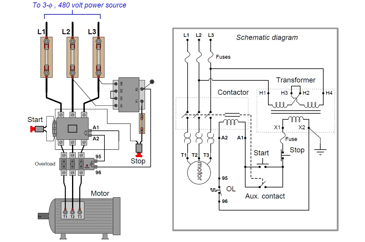
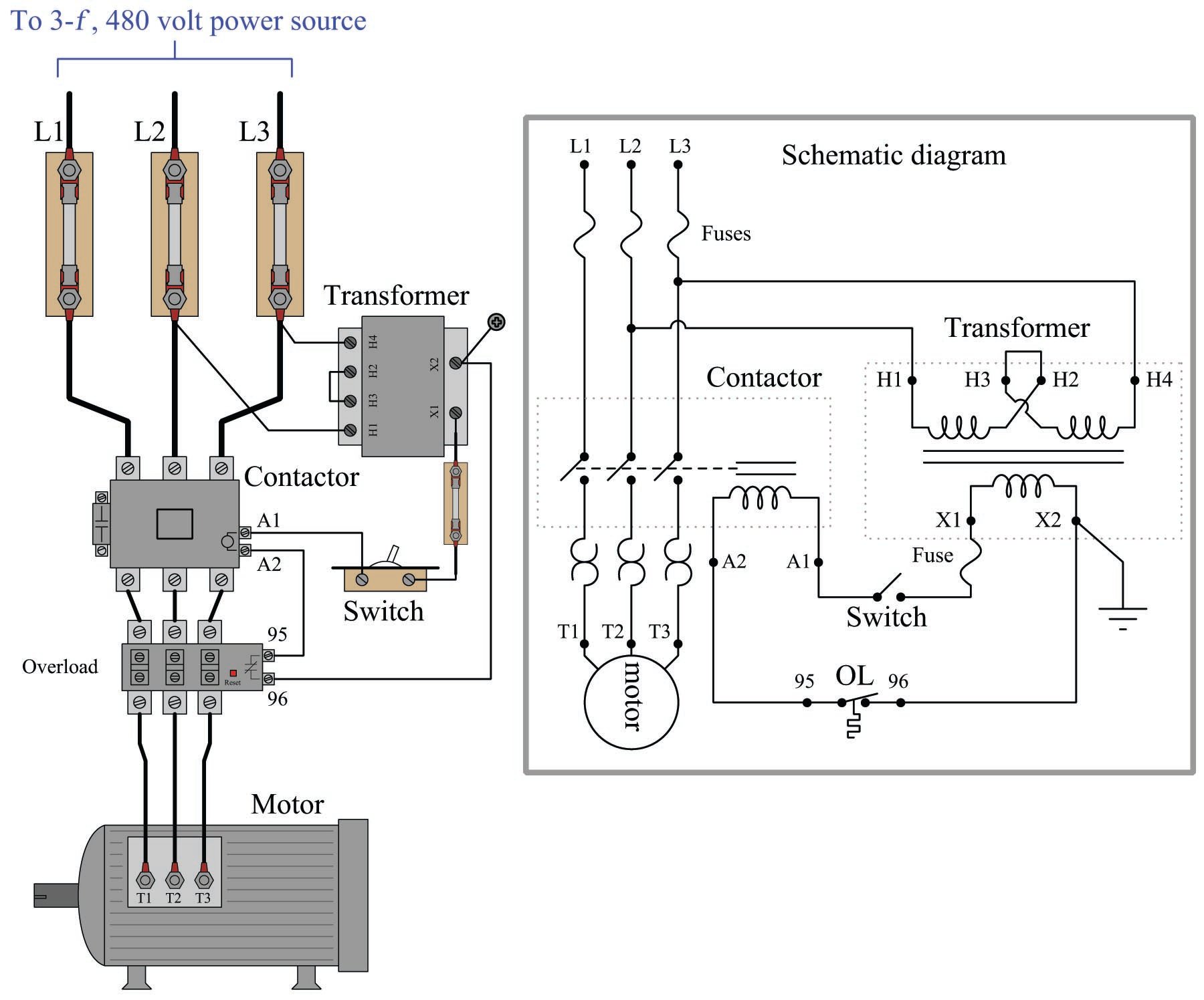
Motor Control Circuit Wiring Instrumentation Tools The control circuit is separate from the motor circuit. the control circuit may not be at the same voltage as the power circuit. when the voltage of the control and power circuits is the same, it is referred to as common control. if the volt ages are different, it is called separate control. figure 4. typical starter wiring diagram — three phase. Wiring diagrams show the connections to the controller. wiring diagrams, sometimes called “ main ” or “ construction ” diagrams, show the actual connection points for the wires to the components and terminals of the controller. basic wiring for motor control – technical data. they show the relative location of the components.

Automatic Motor Control Circuit Diagram Summary. motor contactor (or “starter”) coils are typically designated by the letter “m” in ladder logic diagrams. continuous motor operation with a momentary “start” switch is possible if a normally open “seal in” contact from the contactor is connected in parallel with the start switch, so that once the contactor is energized. There is a “wiring diagram” and adjacent to it a their actual relative positions. all control devices are. “line diagram.”. line diagrams are included because their use is becoming more widespread and we believe shown between vertical lines which represent the source of control power, and circuits are shown. A motor control circuit diagram typically includes various components such as motors, power supplies, control devices, relays, switches, and sensors. these components are interconnected through various electrical connections, such as wires and cables, to form a complete motor control system. the diagram provides a detailed illustration of how. One of the fundamental motor control circuit diagrams is the forward and reverse control diagram. this diagram illustrates how to control the direction of rotation of a motor using a series of switches and relays. understanding this circuit is crucial for applications such as conveyor systems, winches, and automotive electric windows.

Simple Motor Control Circuit Diagram A motor control circuit diagram typically includes various components such as motors, power supplies, control devices, relays, switches, and sensors. these components are interconnected through various electrical connections, such as wires and cables, to form a complete motor control system. the diagram provides a detailed illustration of how. One of the fundamental motor control circuit diagrams is the forward and reverse control diagram. this diagram illustrates how to control the direction of rotation of a motor using a series of switches and relays. understanding this circuit is crucial for applications such as conveyor systems, winches, and automotive electric windows. To achieve two speed, one direction control of a three phase motor using contactors, follow these steps: power & control circuit diagram. draw a schematic diagram and wire the power and control circuit as shown in the figures below. this circuit will consist of a power supply, a low speed contactor (k1), high speed contactors (k2 and k3), a. 10. motor circuits and control.

Comments are closed.