Wiring Diagram Gy6 150cc Wiring Digital And Schematic

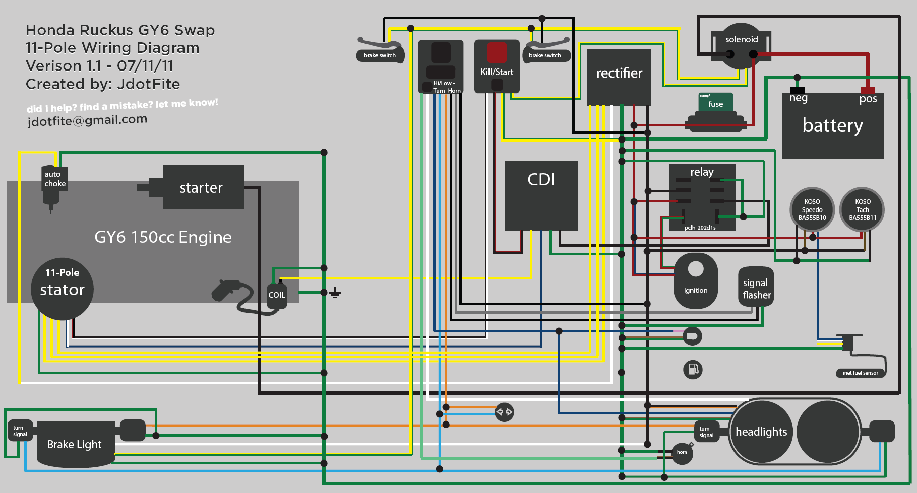
Wiring Diagram Gy6 150cc Wiring Digital And Schematic The gy6 engine wiring diagram is a visual representation of the electrical system of a gy6 engine, which is commonly found in scooters and atvs. it is a detailed diagram that shows the various components of the electrical system and how they are connected and interact with each other. the diagram includes information about the ignition system. Step 4: connect the wires. use wire strippers and crimpers to strip the ends of the wires and attach wire connectors. match the wire colors from the gy6 wiring harness to the corresponding wires on your vehicle, making sure to connect them securely. step 5: solder and insulate.

Gy6 150cc Electrical Wiring Diagram Full electrics wiring harness cdi coil solenoid gy6 150cc atv quad buggy go kart canada. scooter honda gy6 engine bore wiring diagram transpa png. atv wiring harness kit with cdi stator regulator ignition switch solenoid relay for gy6 125cc 150cc 4 stroke parts. tank touring 150cc scooter engine parts extreme motor s inc. The wiring diagram for a gy6 150cc scooter provides a visual representation of how the electrical components are connected and how they communicate with each other. key components: battery: the battery provides power to the scooter’s electrical system. starter motor: the starter motor is responsible for starting the scooter’s engine. The gy6 150cc dc cdi wiring diagram divides the entire system into four sections, each with its own regulatory function. first, there is the ignition control module, which is responsible for controlling the spark plug firing. the second section is the fuel control system, which regulates the amount of gasoline in the combustion chamber. A gy6 engine refers to a type of small, four stroke engine commonly used in scooters, go karts, and other small vehicles. it is named after its design, which features a horizontally mounted cylinder and a 125cc or 150cc engine displacement. the gy6 engine is known for its reliability, ease of maintenance, and availability of aftermarket parts.

Gy6 Wiring Schematic Color Code The gy6 150cc dc cdi wiring diagram divides the entire system into four sections, each with its own regulatory function. first, there is the ignition control module, which is responsible for controlling the spark plug firing. the second section is the fuel control system, which regulates the amount of gasoline in the combustion chamber. A gy6 engine refers to a type of small, four stroke engine commonly used in scooters, go karts, and other small vehicles. it is named after its design, which features a horizontally mounted cylinder and a 125cc or 150cc engine displacement. the gy6 engine is known for its reliability, ease of maintenance, and availability of aftermarket parts. This includes the integration of various sensors, switches, relays, lights, and other electrical devices. in the context of a gy6 150cc go kart, a wiring harness diagram would show the specific layout and connections of the wires for the electrical system of the go kart. this diagram helps in troubleshooting any electrical issues, identifying. One of the key aspects of the gy6 150cc wiring diagram is understanding the color coding system. different wires are identified by different colors, such as red for the ignition switch, yellow for the starter relay, green for the cdi unit, and so on. this color coding makes it easier to identify and trace wires throughout the diagram.

Comments are closed.