Wiring Leds In Parallel Youtube

Parallel Connection Diagram Digital Timer Switch Wiring Wire up any number of leds together for your prop, robot or any electronics project with this comprehensive series vs parallel led circuit design tutorial.📓. Are you about to tackle your first electrical wiring project? not sure where to start? in this video we'll take a deeper dive into electrical wiring and lear.

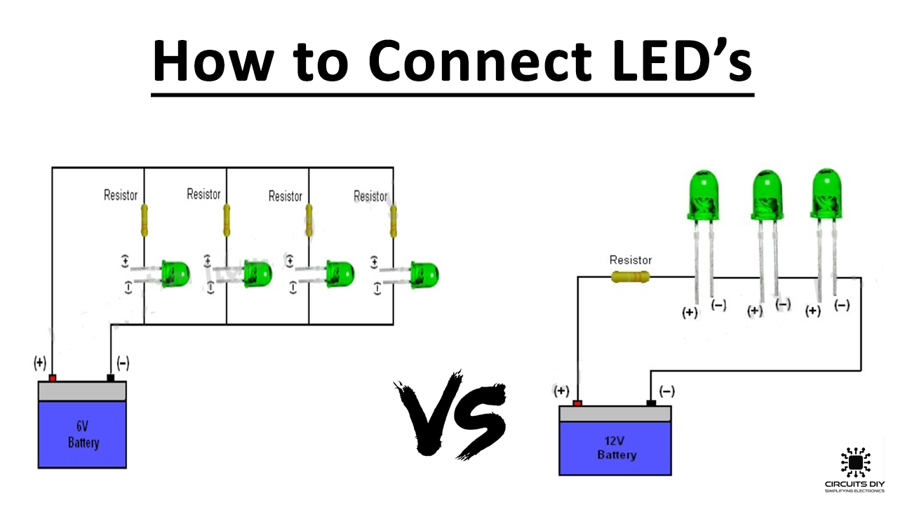
How To Connect Wire Led S Electronic Tutorial An instructional video telling you how to wire leds in a parallel circuit.in this video we have used our contour hd24, further product details can be read he. Parallel circuit: where a series circuit receives the same current to each led, a parallel circuit receives the same voltage to each led and the total current to each led is the total current output of the driver divided by the number of parallel leds. again, don’t worry, here we will see how to wire a parallel led circuit and that should. P = iv p = .020a x 2v since this is being calculated for the resistor we have to say that the current going through the resistor is that of the led (.020a) and the voltage drop is 2v. solving for p = 0.04 watts this is less than a 1 4 watt (.25w), so using a 1 4 watt resistor will work perfectly. Repeat until all leds in the set are connected. connect a resistor to either the anode of the first led in each series set or the cathode of the last led in each series set. now, connect the negative leads (the other side of the series set) to the negative terminal of your power supply.

How To Connect Multiple Leds In Series Parallel Circuit Led Wiring P = iv p = .020a x 2v since this is being calculated for the resistor we have to say that the current going through the resistor is that of the led (.020a) and the voltage drop is 2v. solving for p = 0.04 watts this is less than a 1 4 watt (.25w), so using a 1 4 watt resistor will work perfectly. Repeat until all leds in the set are connected. connect a resistor to either the anode of the first led in each series set or the cathode of the last led in each series set. now, connect the negative leads (the other side of the series set) to the negative terminal of your power supply. Step 3: connect the led cathodes to the negative battery terminal. using a similar strategy to how you connected the positive side, solder a length of wire to the cathode of each led (shorter leads) and combine them into a single wire that gets soldered to the negative wire of the battery pack. When you wire in series, you add the forward voltages of each led in the circuit but the current fed to each led remains the same. if you have 3 led cobs, each with a forward voltage of 36v at a given current, when you wire them in series, the total voltage drop of the circuit becomes 108 volts. if, for example, your led driver produces 1400ma.

Wiring Lights In Series Vs Parallel Step 3: connect the led cathodes to the negative battery terminal. using a similar strategy to how you connected the positive side, solder a length of wire to the cathode of each led (shorter leads) and combine them into a single wire that gets soldered to the negative wire of the battery pack. When you wire in series, you add the forward voltages of each led in the circuit but the current fed to each led remains the same. if you have 3 led cobs, each with a forward voltage of 36v at a given current, when you wire them in series, the total voltage drop of the circuit becomes 108 volts. if, for example, your led driver produces 1400ma.

Wiring In Series And Parallel Diagram

Comments are closed.