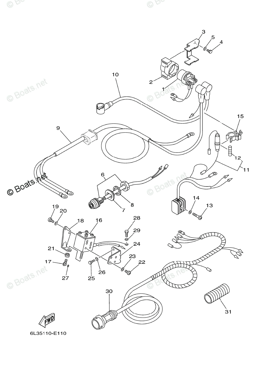
Yamaha 25 Hp Outboard Wiring Diagram Wiring Diagram

Yamaha 25 Hp Outboard Wiring Diagram Wiring Diagram Yamaha outboard motor wiring diagrams typically consist of various symbols and lines that represent different electrical components and their connections. for example, a battery symbol and lines indicate the power source, while different shapes and lines represent switches, circuit breakers, fuses, and wires. these symbols and lines are labeled. Yamaha 25hp outboard wiring diagrams are very important in terms of maintaining and troubleshooting the power supply of your engine. not only do they help in establishing the electrical components, the diagrams also help in finding faults and aiding the diagnosis of certain issues. furthermore, wiring diagrams enable safe maintenance, repair.

25 Hp Yamaha Outboard Wiring Diagram Wiring diagrams for outboard motors. new for 2022! we are building up a repository of free wiring diagrams for outboard motor engines for manufacturers such as johnson, evinrude, mariner, mercury, honda, suzuki, tohahsu and more. troubleshoot your outboard starting or ignition system problems with this essential resource. General information emu25770 start in gear protection yamaha outboard motors or yamaha ap proved remote control units are equipped with start in gear protection device (s). this feature permits the engine to be started only when it is in neutral. always select neutral before starting the engine. Key ‘on’ power yellow wire. the positive terminal of the battery, which has a small blue jumper that will only power the light bulb in the gauge, is where the key ‘on’ power enters. therefore, if you ever see a blue jumper wire, it’s usually only to backlight the gauge with light. thus a positive post here key ‘on’ power will. A yamaha outboard gauge wiring diagram is a schematic representation of the electrical connections and wiring layout for the gauges on a yamaha outboard boat motor. it provides a detailed view of how the gauges are connected to the battery, ignition switch, and various sensors and sensors. the diagram typically includes color codes for the.

Yamaha 25 Hp Outboard Wiring Diagram Wiring Diagram Key ‘on’ power yellow wire. the positive terminal of the battery, which has a small blue jumper that will only power the light bulb in the gauge, is where the key ‘on’ power enters. therefore, if you ever see a blue jumper wire, it’s usually only to backlight the gauge with light. thus a positive post here key ‘on’ power will. A yamaha outboard gauge wiring diagram is a schematic representation of the electrical connections and wiring layout for the gauges on a yamaha outboard boat motor. it provides a detailed view of how the gauges are connected to the battery, ignition switch, and various sensors and sensors. the diagram typically includes color codes for the. Crank position sender; lighting coil lead to rectifier. blue green stripe. main tank oil level sensor sw2 oil transfer circuit. blue red stripe. main tank oil level sensor sw3. no oil warning circuit. blue white stripe. main tank oil level sensor sw1; oil transfer off circuit. Ensure that the connection is tight and secure from any vibrations or movement. connect the ground wire: lastly, connect the ground wire from the trim gauge to the boat’s common ground. this is typically the negative terminal on the boat’s battery or a designated common grounding point on the boat’s electrical system.

25 Hp Yamaha Outboard Wiring Diagram Crank position sender; lighting coil lead to rectifier. blue green stripe. main tank oil level sensor sw2 oil transfer circuit. blue red stripe. main tank oil level sensor sw3. no oil warning circuit. blue white stripe. main tank oil level sensor sw1; oil transfer off circuit. Ensure that the connection is tight and secure from any vibrations or movement. connect the ground wire: lastly, connect the ground wire from the trim gauge to the boat’s common ground. this is typically the negative terminal on the boat’s battery or a designated common grounding point on the boat’s electrical system.

Comments are closed.