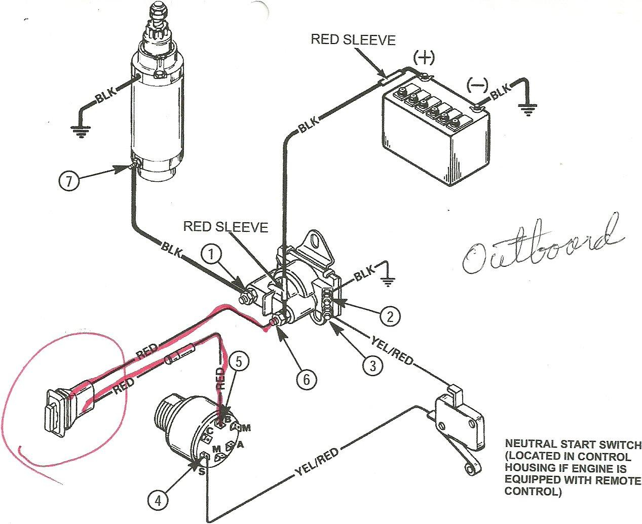
Yamaha Outboard Ignition Switch Wire Diagram

Yamaha Outboard Ignition Wiring Key components: the yamaha outboard ignition switch wiring consists of several key components, including the ignition switch itself, ignition coil, distributor, spark plugs, and battery. these components work together to provide the necessary spark for combustion in the engine cylinders. wiring diagram: a wiring diagram is a helpful tool for. 4. prepare the wires: using wire strippers, strip a small amount off the ends of the key switch wires to expose the bare metal. this will allow for a secure connection when crimping the terminals. 5. crimp the terminals: using wire crimpers, attach the appropriate terminals to the ends of the key switch wires.

Yamaha Outboard Ignition Switch Wiring Diagram Wiring D Before diving into the wiring diagrams, it’s important to take a look at the basic components of a yamaha outboard ignition switch. the main pieces include the key switch, the wire harness, and the power cables. together, these three parts make up the complete circuit. the key switch is a small switch located on the dashboard. Affiliate links:buy the yamaha ignition switch replacement here amzn.to 3gzdmgb. Yamaha outboard motor wiring diagrams typically consist of various symbols and lines that represent different electrical components and their connections. for example, a battery symbol and lines indicate the power source, while different shapes and lines represent switches, circuit breakers, fuses, and wires. these symbols and lines are labeled. Tweet. #3. 04 04 2011, 08:31 am. here is a chart with yamaha wire colors. wiring where used color codes for yamaha outboard boat motors. outboards do not need 12v run from ignition switch back to motor to make it to stay running, you just ground the kill wire when you want it to stop running. so you will need a 12v (red)wire,a start (brown.
Yamaha Outboard Ignition Switch Wiring Diagram Wiring D Yamaha outboard motor wiring diagrams typically consist of various symbols and lines that represent different electrical components and their connections. for example, a battery symbol and lines indicate the power source, while different shapes and lines represent switches, circuit breakers, fuses, and wires. these symbols and lines are labeled. Tweet. #3. 04 04 2011, 08:31 am. here is a chart with yamaha wire colors. wiring where used color codes for yamaha outboard boat motors. outboards do not need 12v run from ignition switch back to motor to make it to stay running, you just ground the kill wire when you want it to stop running. so you will need a 12v (red)wire,a start (brown. Yamaha outboard ignition switch wiring diagrams are typically found in the owner’s manual. these diagrams provide an easy to follow visual representation of the wiring connections between the ignition switch, the engine’s electrical system, and the battery. the diagrams are typically color coded to make it easier to identify the various. Crank position sender; lighting coil lead to rectifier. blue green stripe. main tank oil level sensor sw2 oil transfer circuit. blue red stripe. main tank oil level sensor sw3. no oil warning circuit. blue white stripe. main tank oil level sensor sw1; oil transfer off circuit.

Yamaha Outboard Ignition Switch Wire Diagram Yamaha outboard ignition switch wiring diagrams are typically found in the owner’s manual. these diagrams provide an easy to follow visual representation of the wiring connections between the ignition switch, the engine’s electrical system, and the battery. the diagrams are typically color coded to make it easier to identify the various. Crank position sender; lighting coil lead to rectifier. blue green stripe. main tank oil level sensor sw2 oil transfer circuit. blue red stripe. main tank oil level sensor sw3. no oil warning circuit. blue white stripe. main tank oil level sensor sw1; oil transfer off circuit.

Comments are closed.