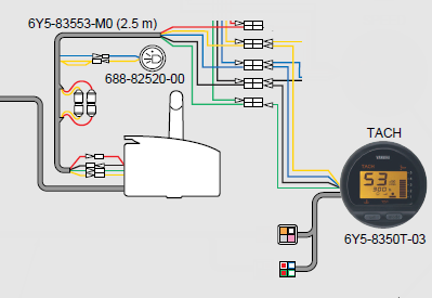
Yamaha Outboard Tachometer Wiring Diagram How To Wire It

Yamaha Outboard Tachometer Wiring Diagram How To Wire It Follow the steps below to install your outboard yamaha tachometer. step 1: use a screwdriver to turn the selector switch to match the number of poles in your alternator for the correct rpm calibration. if you don’t know the number, consult the outboard tachometer application chart. step 2: to the tach stud marked “bat,” connect a yellow. The wiring diagram will show how these components are connected to each other and to the outboard’s power source. step 4: trace the wires. using the wiring diagram as a guide, trace the paths of the wires involved in the tachometer circuit. pay close attention to the connections and ensure that they are correctly made.

Yamaha Outboard Digital Tach Wiring Diagram Step 1: gather the necessary materials. before starting the wiring process, make sure you have all the necessary materials. this includes a tachometer compatible with yamaha outboard engines, a wiring harness, electrical connectors, a socket set, wire strippers, and a multimeter. Now that you know which wiring color leads to what function in your yamaha outboard, let’s take a look at the diagram first; before we go into practice, you should have a volt meter, speedometer, fuel gauge, and, lastly, the tachometer in front of you now. in this instance, we’re going to begin at the position of the gauge harness. I have a 2003 yamaha 115 2 stroke txrb with the 703 control box. i am trying to install a 6y5 8350t d0 00 tachometer. i used the 6y5 83553 n0 00 gauge harness 2 fuse kit and the 68f 82553 70 00 2 plug wire harness from motor to the 2 plug tachometer. everything seems to be working on the tachometer except the temperature icon on the gauge has. Section 1: understanding yamaha digital tachometer wiring. the yamaha digital tachometer is an important component in monitoring the performance of your yamaha outboard motor. to ensure it is properly wired, it is important to understand the wiring diagram and follow a step by step guide. wiring diagram: the wiring diagram provides a visual.

Yamaha Outboard Tachometer Wiring I have a 2003 yamaha 115 2 stroke txrb with the 703 control box. i am trying to install a 6y5 8350t d0 00 tachometer. i used the 6y5 83553 n0 00 gauge harness 2 fuse kit and the 68f 82553 70 00 2 plug wire harness from motor to the 2 plug tachometer. everything seems to be working on the tachometer except the temperature icon on the gauge has. Section 1: understanding yamaha digital tachometer wiring. the yamaha digital tachometer is an important component in monitoring the performance of your yamaha outboard motor. to ensure it is properly wired, it is important to understand the wiring diagram and follow a step by step guide. wiring diagram: the wiring diagram provides a visual. Step 1: locate the ground wire in the wiring harness. this wire is often black or has a black stripe and is typically connected to the negative terminal of the battery or a metal grounding point on the engine. step 2: strip a small portion of insulation from the end of the ground wire using wire strippers. Begin by connecting the wiring harness to the back of the yamaha outboard digital gauges. ensure that each wire is securely connected according to the wiring diagram. use wire strippers cutters to strip the ends of the wires for a clean connection. 4. connect the wiring harness to the control box and engine.

Comments are closed.