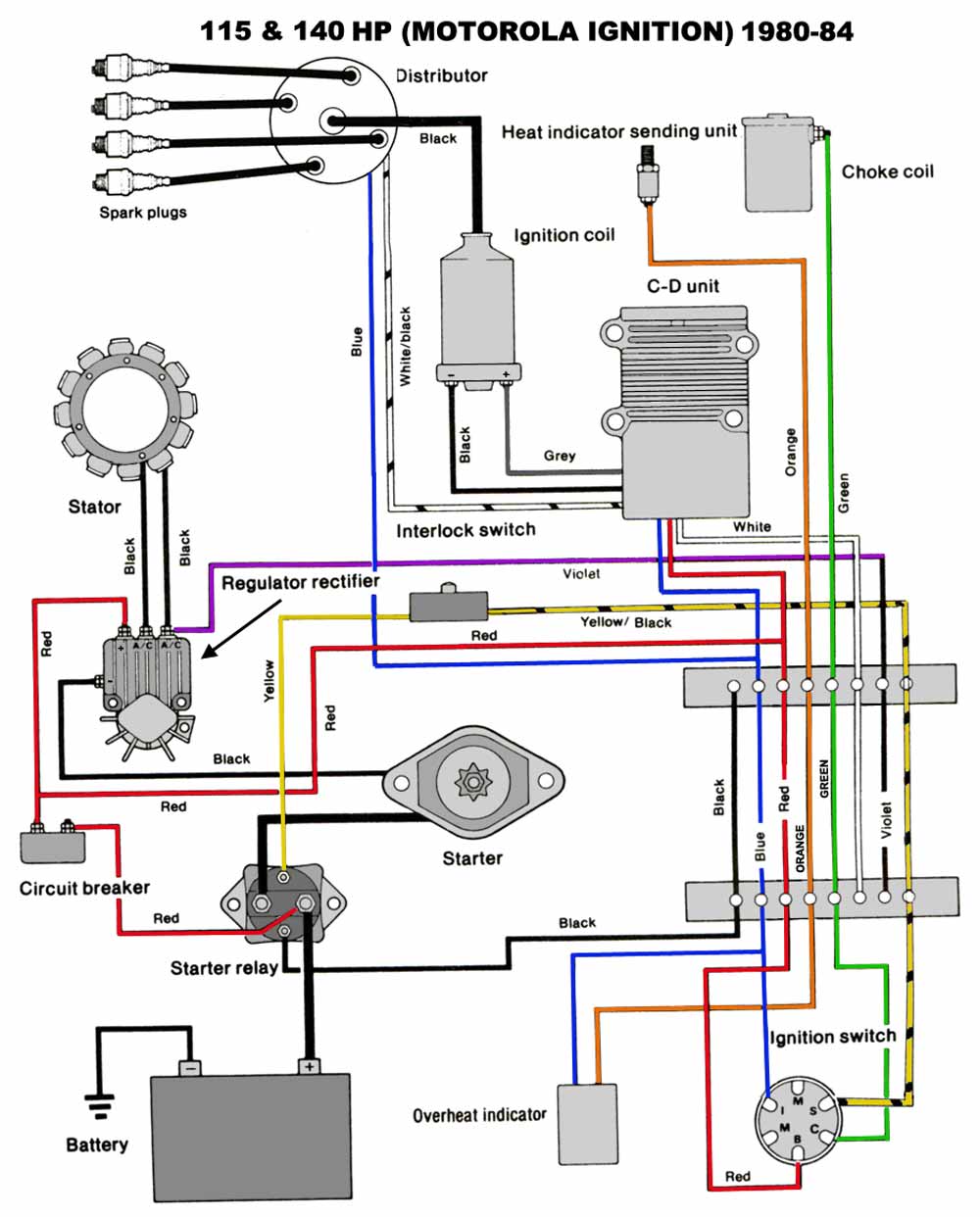
Yamaha Outboard Wiring Diagram Iot Wiring Diagram

Yamaha Outboard Digital Tach Wiring Diagram Yamaha outboard motor wiring diagrams typically consist of various symbols and lines that represent different electrical components and their connections. for example, a battery symbol and lines indicate the power source, while different shapes and lines represent switches, circuit breakers, fuses, and wires. these symbols and lines are labeled. Tweet. #50. 01 30 2013, 06:38 pm. yamaha outboard digital multi function speedometer. my boat has a yamaha outboard digital multi function speedometer. it displays the speed, distance traveled, battery status, and fuel tank level. i think the part number is #6y5 2818r 30. the fuel tank level indication does not work.

Yamaha Outboard Wiring Diagrams Key ‘on’ power yellow wire. the positive terminal of the battery, which has a small blue jumper that will only power the light bulb in the gauge, is where the key ‘on’ power enters. therefore, if you ever see a blue jumper wire, it’s usually only to backlight the gauge with light. thus a positive post here key ‘on’ power will. Tweet. #6. 01 02 2010, 08:17 am. need some diagrams. would it be possible for someone to email me a wiring diagram for a 2 combo gauges. 1 being speed (trip, time,batt) 6y5 83570 s5 00. 2nd being tach (trim, oil and temp) 6yr w0035 e2 00. as i need to re wire mine and cant find a diagram anywhere. thanks in advance. Follow the steps below to install your outboard yamaha tachometer. step 1: use a screwdriver to turn the selector switch to match the number of poles in your alternator for the correct rpm calibration. if you don’t know the number, consult the outboard tachometer application chart. step 2: to the tach stud marked “bat,” connect a yellow. Red oil warning light ground through sw3 in main tank oil. sensor to tachometer. green white stripe. crank position sender; lighting coil lead to rectifier. blue green stripe. main tank oil level sensor sw2 oil transfer circuit. blue red stripe. main tank oil level sensor sw3. no oil warning circuit.

Comments are closed.